9.2 COMMUNICATION CABLE PINOUT AND DIP SWITCH ID TABLES
EG4
®
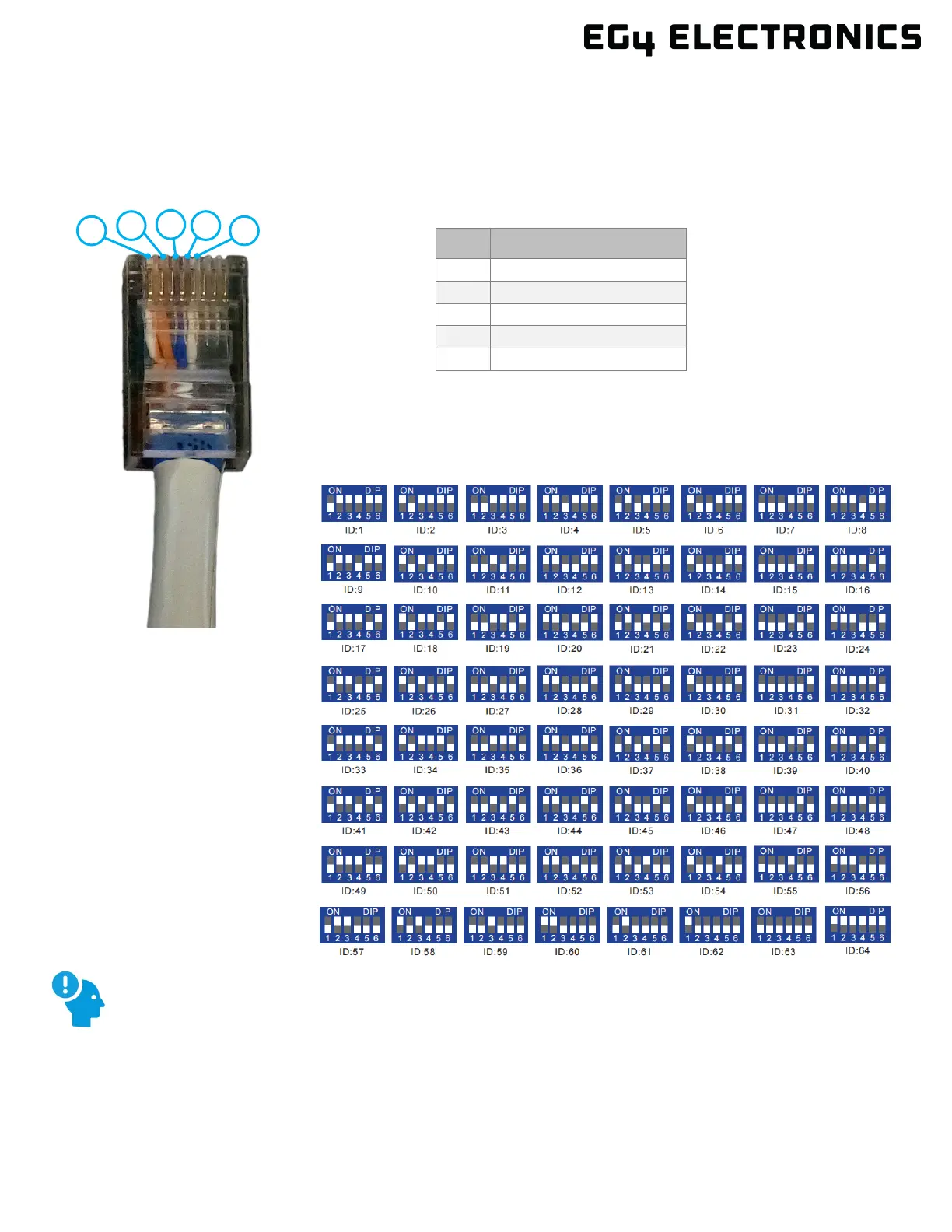
LifePower4 48V V2 batteries interface with an inverter by designating a “Host” battery (DIP
switch ID No. 1). The ID code range is 1 ‒ 64 and the communication mode can support up to 64
modules in parallel.
PIN DESCRIPTION
When paralleling multiple batteries, all DIP switch settings must be different from each other.
This allows all equipment to see each battery in the bank separately. EG4 recommends
addressing the batteries in ascending order.
switch ID table – 6 Pin
*Pinouts are for battery side;
please refer to the system
manual for pinout
configuration on system end