8.3 INSTALLATION IN EG4 BATTERY RACK
1. Insert the battery into the rack slot, beginning with the
bottom slot and progressing upward. Slide in until the
battery is firmly seated in the rack.
2. Use the included 4 AWG power cable to
connect each battery to the busbar.
3. DO NOT finger tighten the battery or
busbar terminal bolts. The battery bolts
require a certain torque [60 in-lbs. (6.8Nm)]
to ensure they do not loosen during
operation. Failure to properly tighten the
terminal bolts can result in serious damage
and will void the warranty.
4. Clearly identify the location of the batteries
positive and negative terminals—red to the
positive terminal and black to the negative
terminal. Then connect to the inverters
positive and negative terminals.
Grounding
Attach a grounding wire from the rack/cabinet
to an equipment grounding conductor, then
terminate the EGC at a grounding electrode.
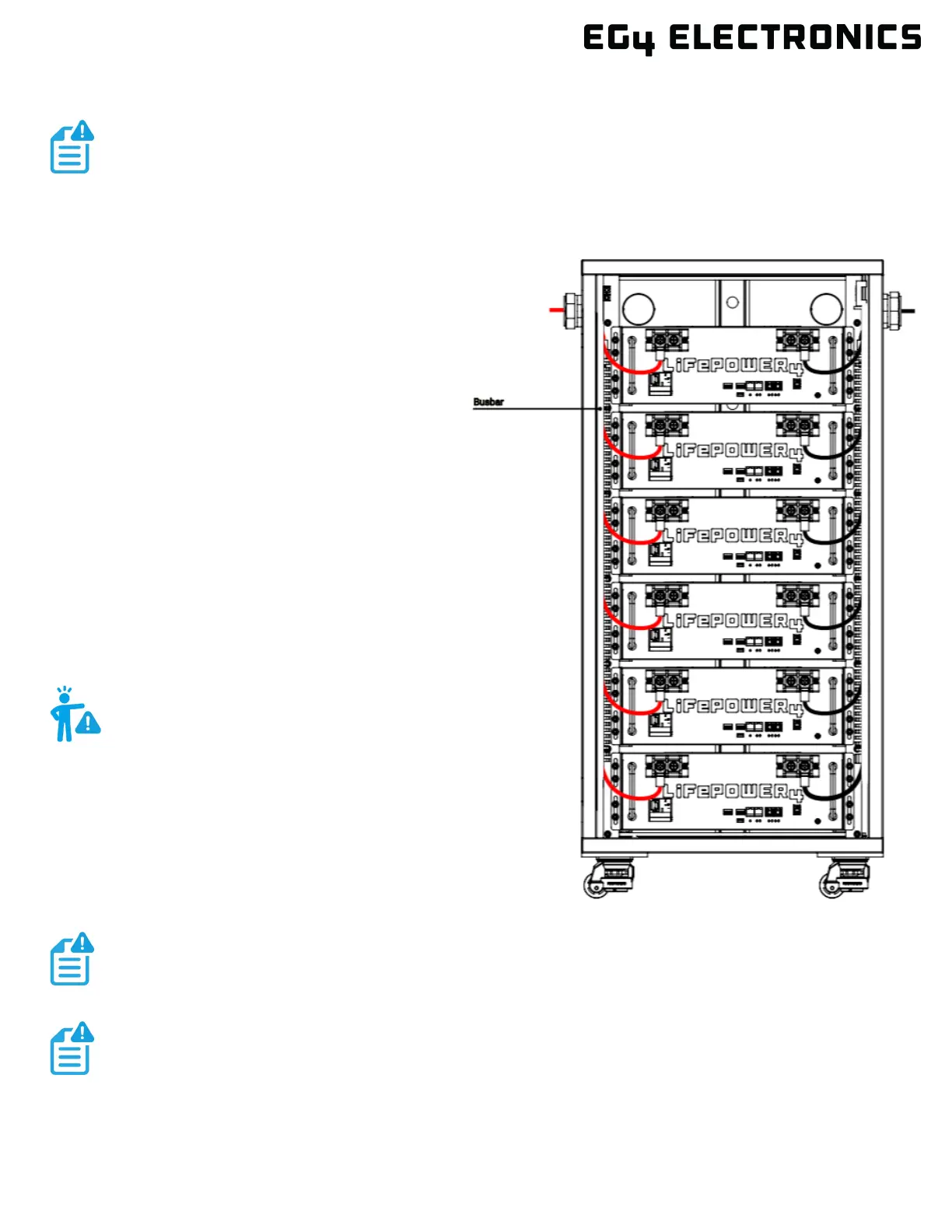
In this image, there are 6 LifePower4 V2
100Ah batteries wired in parallel. This battery
bank still maintains the appropriate 48V
needed for a system. However, the amp hour
rating of this bank has increased to 600Ah. In
addition, the potential output amperage of the
rack increases.
NOTE:
The image below represents 6 EG4
®
LifePower4 V2 batteries with an EG4 Welded Indoor
Cabinet. When installing multiple batteries or adding a battery to an existing rack, please
ensure each battery is charged individually to 100% before paralleling them together. This
step is crucial to optimize battery performance and ensure proper operation.
WARNING:
Do not ground rack/cabinet or door to
negative or positive bus bars!
Use the included battery cables or size the battery cables appropriately! Refer to an NEC
approved ampacity chart for specifications.
EG4 recommends using a properly sized (amp rated) busbar to parallel batteries together.
Paralleling via the battery terminals will cause inconsistent charging and discharging issues