product operating instruction
E.G.O. Germany (E.G.O. Elektro-Gerätebau GmbH)
document id.: 90.60160.286-001-04-A / state: 230 - released
designation: Induction Gx
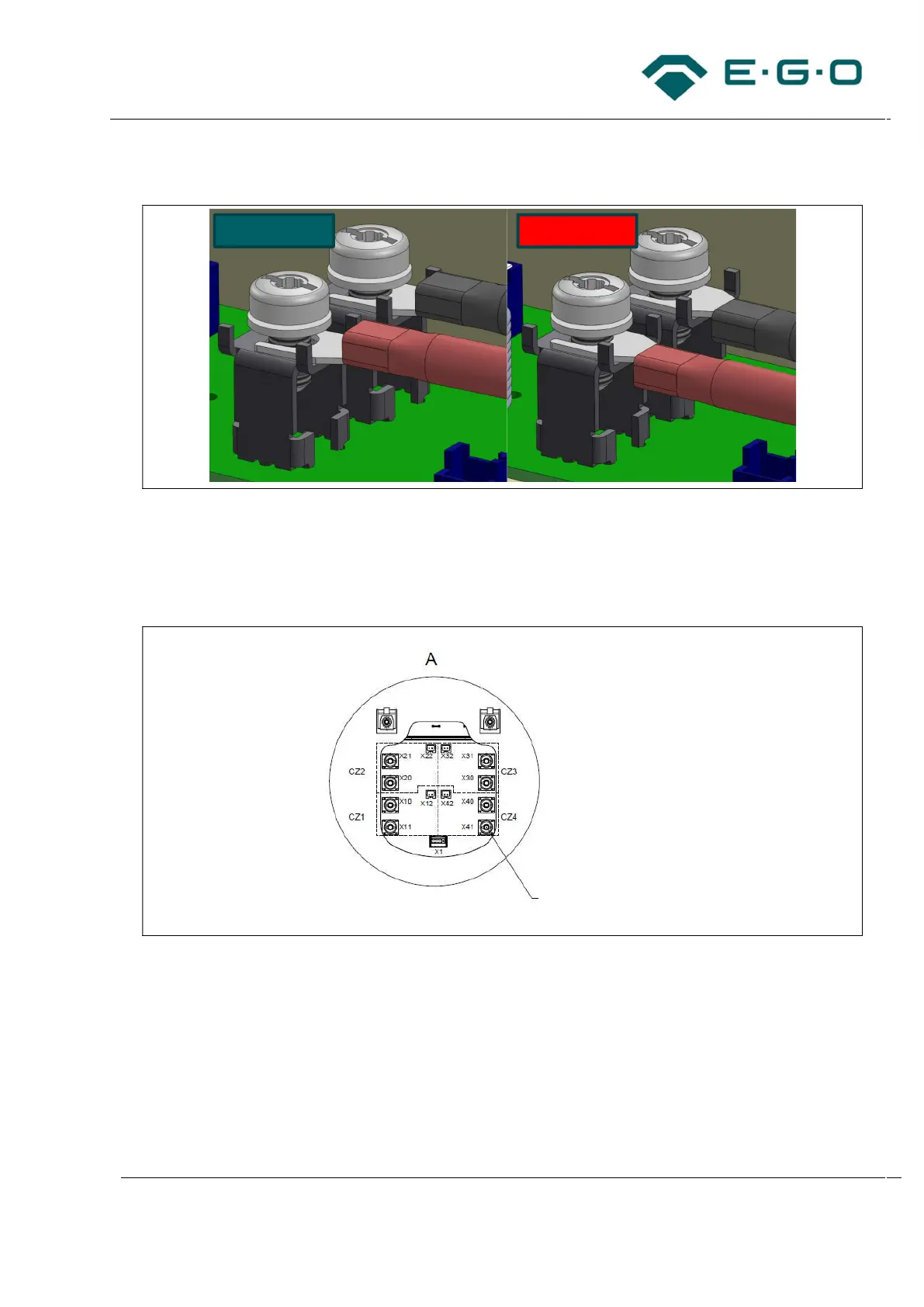
15 Exemplary illustration of crimp contact direction
– It must be ensured that the allocation between temperature sensor and inductor power cable is
kept.
– Fasten the terminal screws with a tightening torque of 1.9 Nm + 0.2 Nm – 0.4 Nm.
16 Exemplary illustration of terminals for inductors on a 4-burner generator
The maximum induction power of coil and generator converter must be equal.
– Connect NTC wire only to the corresponding NTC connector (e.g., x12/x22/x32/x42).
– Connect the black wire only to the corresponding black connector (e.g., x11/x21/x31/x41).
– Connect the blue wire only to next connector (e.g., x10/x20/x30/x40).
– Repeat the steps for further inductors.
Correct
Wrong
M
a
=1.9 Nm + 0.2 Nm -0.4 Nm