product operating instruction
E.G.O. Germany (E.G.O. Elektro-Gerätebau GmbH)
document id.: 90.60160.286-001-04-A / state: 230 - released
designation: Induction Gx
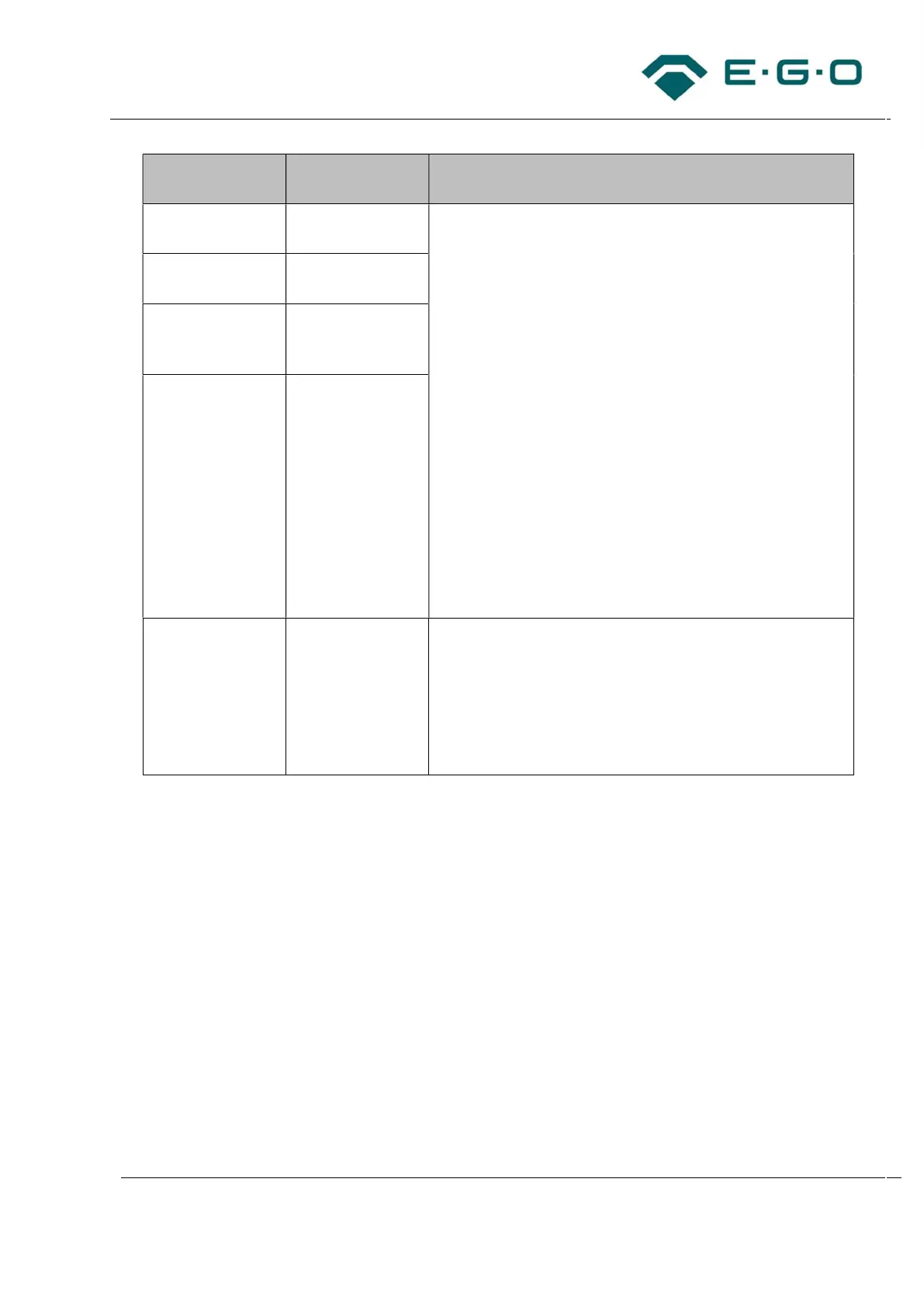
Description of
objects
Recommended
distances
Comments
Inductor to TC
Slim SK
Minimum: 20 mm The distances are based on the outer edge of the inductor’s
mica sheet to the outer edge of the user interface’s PCB or
the edge of the electrically conductive material / metal
frame. The user interfaces – especially those one with
SmartKii technology – are sensitive for overtemperatures.
When going beyond the recommended minimum distances,
make sure that:
the sensitivity of the touch buttons is not influenced
significantly.
not to exceed the max. allowed temperature for the
user interface (see customer documentation and
customer drawing of the corresponding user interface)
not to exceed the max. allowed temperature on the
glass ceramic’s surface above the user interface (60 °C
according to EN 60335 section 11.7).
the performance and lifetime are secured.
the standards (safety, EMC, usability, efficiency,
environments, approvals) of the technical customer
documentation Gx and of the user interface are fulfilled.
Inductor to TC Lite
Slider SK
Minimum: 20 mm
Inductor to TC
VArio SK (master
and slaves)
Minimum: 20 mm
User interface to
adjacent
electrically
conductive
materials
Minimum: 10 mm
Inductor to metal
frame (surrounding
the glass ceramic)
Minimum: 5 mm
(relating to an
aluminum frame),
10 mm or
individual testing
(for other
materials)
The distances are based on the outer edge of the inductor’s
mica sheet to the outer edge of the metal frame.
Tab. 5: Distances
4.1.1 Exemplary assembly of a 4-burner hob with Gx induction
The following steps must be considered for the fixation of mounting plate and induction generator.
1. Align the mounting plate with the screw holes of the generator.
– The mounting plate must be assembled directly on the housing of the generator. The gap
between the mounting plate and the must be as small as possible to avoid a reduction of
cooling and performance.
– Consider all correct alignment positions as shown in the following illustration.