product operating instruction
E.G.O. Germany (E.G.O. Elektro-Gerätebau GmbH)
document id.: 90.60160.286-001-04-A / state: 230 - released
designation: Induction Gx
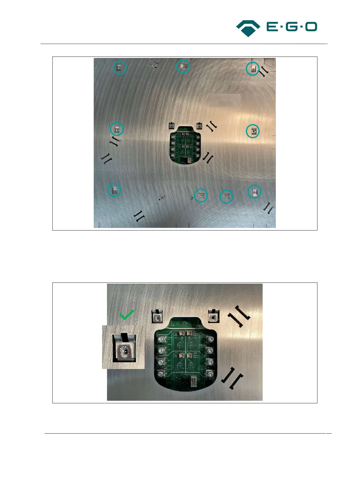
3 Positions for assembling the generator to the mounting plate
– Consider the correct alignment as shown in the following illustration. The mounting plate cut-out
for the inductor terminals and NTC and user interface connectors must be accessible and
correct positioned. Thermal and electric requirements must be fulfilled by the design of the cut-
out.
4 Correct alignment
– An alignment as shown below is not allowed.