product operating instruction
E.G.O. Germany (E.G.O. Elektro-Gerätebau GmbH)
document id.: 90.60160.286-001-04-A / state: 230 - released
designation: Induction Gx
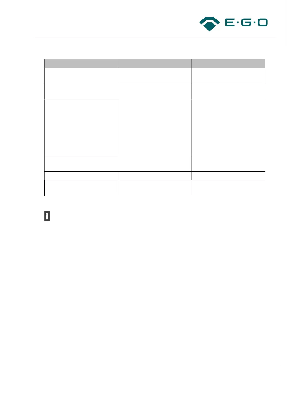
Necessary accessories:
Description of accessory Type number of references Drawings of references
Cover for connection box of the
generator (VDE)
98.403.08 C000040984
Stranded cable 4-pin, twisted,
235 mm (Bus cable for UI)
95.501.12 -
Clamp terminal (recommended
for thin cables
7-14 mm
depending on insulation material
condition) for 4-burner generator
Clamp terminal (recommended
for thick cables ø13-20 mm
depending on insulation material
condition) for 4-burner generator
98.403.12
98.403.13
C000040890-002
C000041074-002
Clamp terminal (optional for 2-
burner generator)
75.177.63/01 90.03302.351
Connection bridge 75.97009.001 75.97009.001
Transportation pin (exemplary
TC Lite Slider SmartKii)
969.319 C000056393
Tab. 7: Necessary accessories for electrical connection
Tip: Stranded wires are available for samples, but not in series scope of delivery. The stranded wire
type is depending on the type of components as user interfaces and distances.
4.2.1 Power supply for bus participants
10 W are provided for user interfaces and other bus participants as well as for other suitable
accessories (e.g., EGO Light Elements) These can be split into a rated voltage of 5 V or 13.2 V for
supply of user interfaces.
4.2.2 Exemplary electrical connection of a 4-burner hob with Gx induction
The following steps must be considered for electrical connection.
1. Do the assembly as described exemplary in chapter 4.1.1.
2. Perform the fastening and wiring of inductors by considering the remarks below. It is recommended
to start the wiring with the temperature sensor cables and both cooking zones next to fans.
– Consider connection diagram of the related type data sheet.
– The black inductor terminal must be connected to the black position on the printed circuit board
always. This is necessary for EMC reasons.
– The crimped cable part must be faced upwards. It must be avoided that the cable lug’s
shrinking hose has contact to the adjacent cable lug.