product operating instruction
E.G.O. Germany (E.G.O. Elektro-Gerätebau GmbH)
document id.: 90.60160.286-001-04-A / state: 230 - released
designation: Induction Gx
NOTICE! The assembly of the user interface is depending on each product family. Consider the
customer documentation of the corresponding user interface for details.
19 Exemplary positioning of TC Lite Slider SmartKii
– Connect EGO Bus wire to the connector of the touch control. Cables must be laid on the direct
direction from the mounting plate cut-out of the generator connectors. Cable routings must be
done completely on the mounting plate. Cables must be drilled minimum four up to maximum
ten times (complete turns). The four single wires must be routed and fixed together. It must be
avoided that cables are routed under the user interfaces or mounting plate, especially in the
position of the generator IGBTs and resonant circuits. Cables of inductors and user interfaces
must be laid as far as possible from each other. Parallel routings of user interface and inductor
cable must be avoided.
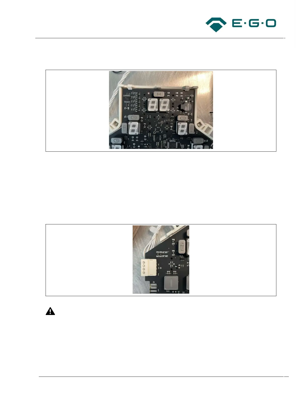
20 Exemplary connection of EGO Bus wire to the touch control
CAUTION! Risk of damaging the induction generator and touch control. A damaged EGO Bus
cable (e.g., truncated insulation) may cause voltage flashover from low voltage to extra-low voltage
side, e.g., during high voltage test.
The EGO Bus cable must not be jammed, kinked or guided over sharp edges.