E L A N H O M E S Y S T E M S
© ELAN Home Systems 2009 • All rights reserved. Page 17
A12 INSTALLATION MANUAL
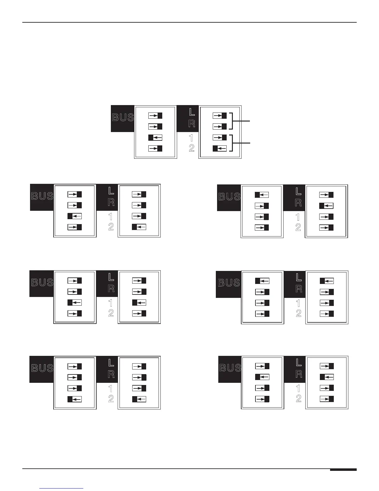
DIP Switch Settings
The four DIP switches correspond (from top to bottom) to Bus Left, Bus Right, Direct Input Left, and Direct Input
Right. Flip the switch to the left to enable the setting, to the right to disable it. Only one setting should be enabled
(set to the left position) at a time. Carefully review the diagrams below before setting DIP switches.
L
R
1
2
BUS
Factory Default DIP Switch Settings
BUS INPUT
Dipswitches
DIRECT INPUT
Dipswitches
L
R
1
2
BUS
Direct Input-Stereo (Factory Default)
L
R
1
2
BUS
Bus Mode-Stereo
L
R
1
2
BUS
Direct Input-Mono
(Sending CH. 1, 3, 5, 7, 9, or 11 to CH. 2, 4, 6, 8, 10, or 12)
L
R
1
2
BUS
Bus Mode-Mono
(Sending Left Bus Input to Left & Right Channels)
L
R
1
2
BUS
Direct Input-Mono
(Sending CH. 2, 4, 6, 8, 10, or 12 to CH. 1, 3, 5, 7, 9, or 11)
L
R
1
2
BUS
Bus Mode-Mono
(Sending Right Bus Input to Left & Right Channels)
Figure 3-7: DIP Switch Settings