E L A N H O M E S Y S T E M S
© ELAN Home Systems 2009 • All rights reserved. Page 19
A12 INSTALLATION MANUAL
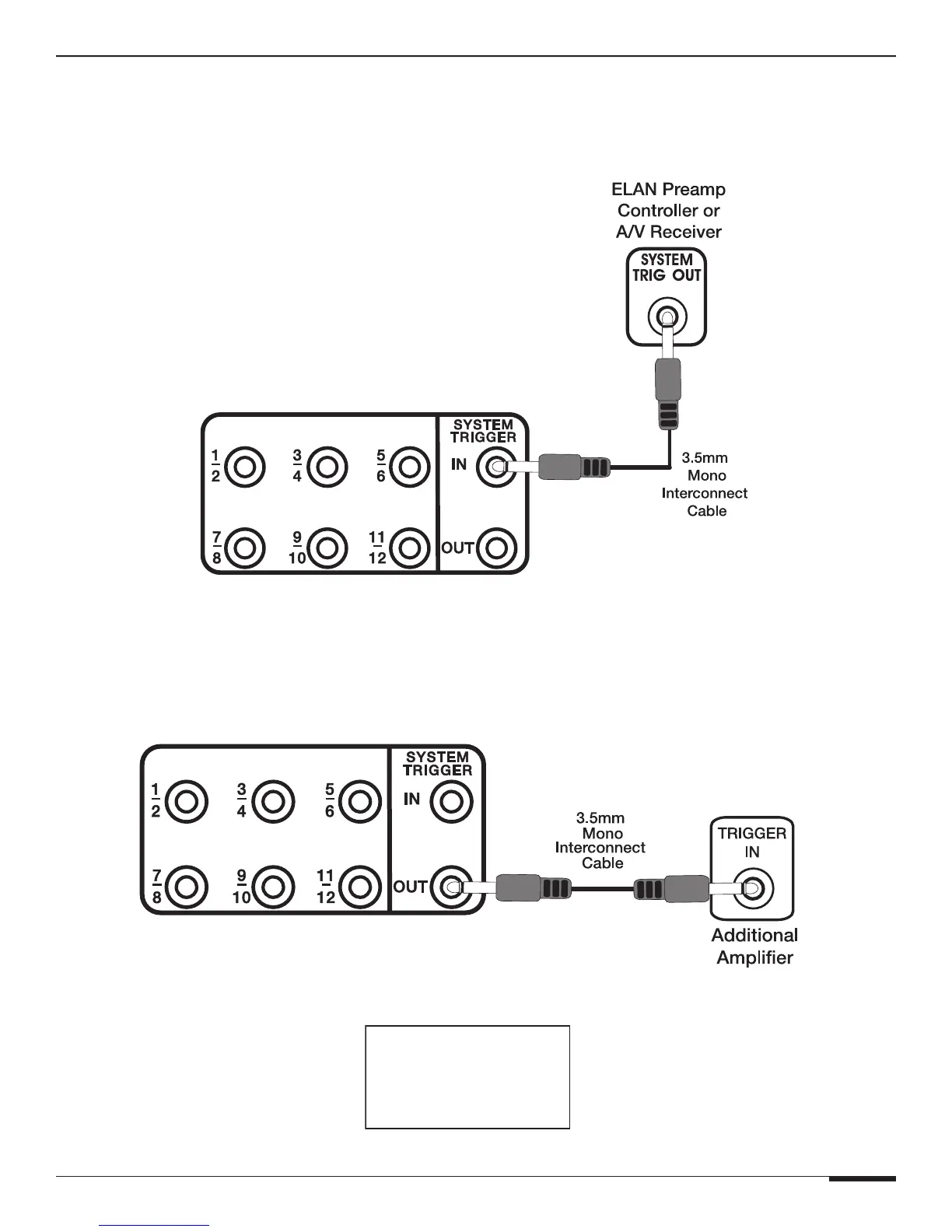
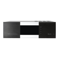
SYSTEM TRIGGER IN
To mute/un-mute all channels simultaneously, connect a system-wide 5-24 Volt DC triggering source to the SYSTEM
TRIGGER IN port using a 3.5mm mono interconnect cable. Examples of triggering sources include an ELAN Multi-
Zone Controller’s SYSTEM TRIGGER OUT or REMOTE OUT, an A/V receiver’s switched outlet connected to a power
supply, or a +12VDC TRIGGER OUT from another ELAN amplifier.
TRIGGER INPUTS
Figure 3-9: System Trigger In
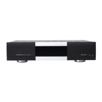
SYSTEM TRIGGER OUT
Whenever the A12 is powered On an any channel is On, the SYSTEM TRIGGER OUT becomes active. This output
sends a +12VDC 100mA signal to other devices with a Trigger Input. Examples of proper usage of the SYSTEM TRIG-
GER OUT include muting/un-muting other amplifiers, triggering the switched outlets of a Z•Power Controller, or trig-
gering automated events using ELAN
®
Sense Sensors and VIA! SR-1 or VIA!2-SS1 devices.
TRIGGER INPUTS
Figure 3-10: System Trigger Out
TRIGGER INPUTS
ACCEPT
5-24 VOLTS DC