E L A N H O M E S Y S T E M S
Page 20 © ELAN Home Systems 2009 • All rights reserved.
A12 INSTALLATION MANUAL
Speaker Connections
Six removable flip-lock connectors allow for easy speaker wire terminations for up to twelve speakers. Use 28-16
AWG stranded copper speaker wire to connect from a zone's speaker location to the output terminal of an A12
amplifier.
+-+ -
L R
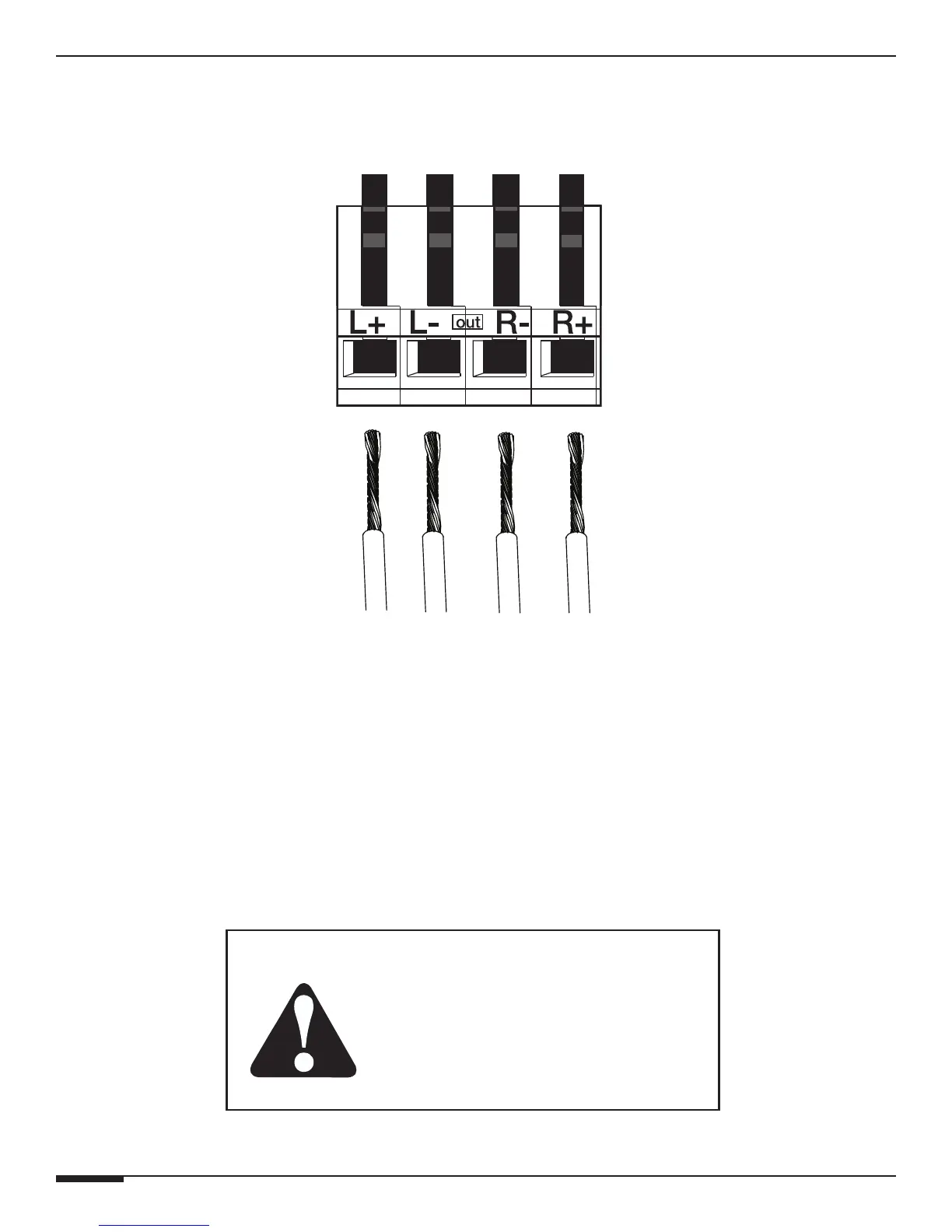
Figure 3-11: Speaker Flip-Lock Terminal Connection
To make connections:
1. Cut the ends of the wire to length, allowing some free play (about 6 inches of slack) to allow for movement
when physically connecting the wire.
2. Using wire strippers, remove 1/2 inch of insulation, then twist the wire to ensure that no stray strands are
evident.
3. Define positive (+) and negative (-) at the amplifier end and the speaker end of the wire run and use the same
conductor on each end.
4. Lift up each flip-lock connector until it is locked in the up position. Place the bare lead from each speaker wire
into the holes of the flip-lock terminal of the A12, maintaining the polarity of each lead (+ to +, - to -).
• Use 28-16 AWG Stranded Copper Speaker Wire
• Amplifier is Rated at 8 Ohms.
Do Not Configure Impedance Below 8 Ohms.
• The amplifier is NOT bridgeable. Do NOT
attempt to bridge or combine channels.
Important Notes: