12
User GuideRG-1000e Remote Gateway
The Ethernet port can work with both automatic and fixed cable type detection, thus, both a straight-through cable
or a crossed Ethernet cable can be used.
Both the radioserver and the RG-1000e GATEWAY must have a static IP address.
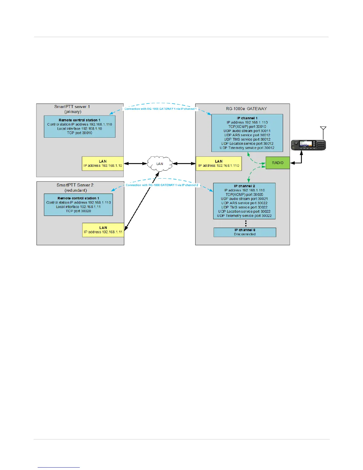
The example of the network configuration for the radioserver and the RG-1000e GATEWAY is shown in the figure
below.
Fig. 2 Connection of the radioserver to the RG-1000e GATEWAY (single radio) via the local data transmission network
In this example, the radioserver is connected to a single RG-1000e GATEWAY to manage one control station,
which is connected to the RADIO interface. Only one configured IP channel is used to transmit data to the
radioserver.
RG-1000e GATEWAY IP channel 1 is programmed to be linked to the RADIO interface, so that all control
commands and audio signals between the RG-1000e GATEWAY and the radio, connected to this interface, are
transmitted to the radioserver via IP channel 1.
The IP address and TCP (XCMP) port of the IP channel are specified in the remote control station settings.
The radioserver initiates the connection with the RG-1000e GATEWAY via TCP protocol linking to preset the IP
address and TCP port. The radioserver selects a random port from a range of 1025...65535 as the TCP source
port.
After establishing the TCP connection, the RG-1000e GATEWAY and the radioserver exchange data packets,
containing the parameters of each of them. Particularly, the RG-1000e GATEWAY sends the following settings of
the ports: audio signals and service data.
When a package with the RG-1000e GATEWAY parameters is received, the radioserver opens the required
number of UDP ports on its side: one UDP port—for audio signals, and one UDP port—for each corresponding