17
4.1 Front panel
User GuideRG-1000e Remote Gateway
4 Installation and connection
4.1 Front panel
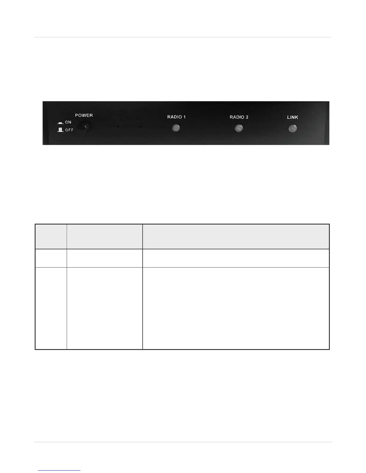
The front panel of the RG-1000e GATEWAY is shown in the figure below.
Fig. 7 Front panel of the RG-1000e GATEWAY
In this figure, the following nomenclature applies:
POWER: The power button
RADIO 1, RADIO 2, LINK: LED indicators, the functions of which are presented in table 2 below
Table 2 Functions of the front panel indicators
· Flashing for about 1000 milliseconds - waiting for connection.
· Turn on - IP connection is established.
· Turn on — the interface is locked:
o there is no connection to IP channels, or
o the radio is not ready (for example, no power supply or the radio
is turned off).
· Slow flash (1 s) - the interface is ready, but the control terminal is
not connected to the IP channel.
· Off - the interface is ready, at least one control terminal is
connected.
· Flashing - data transmission through the interface.