18
4.2 Rear panel
User GuideRG-1000e Remote Gateway
4.2 Rear panel
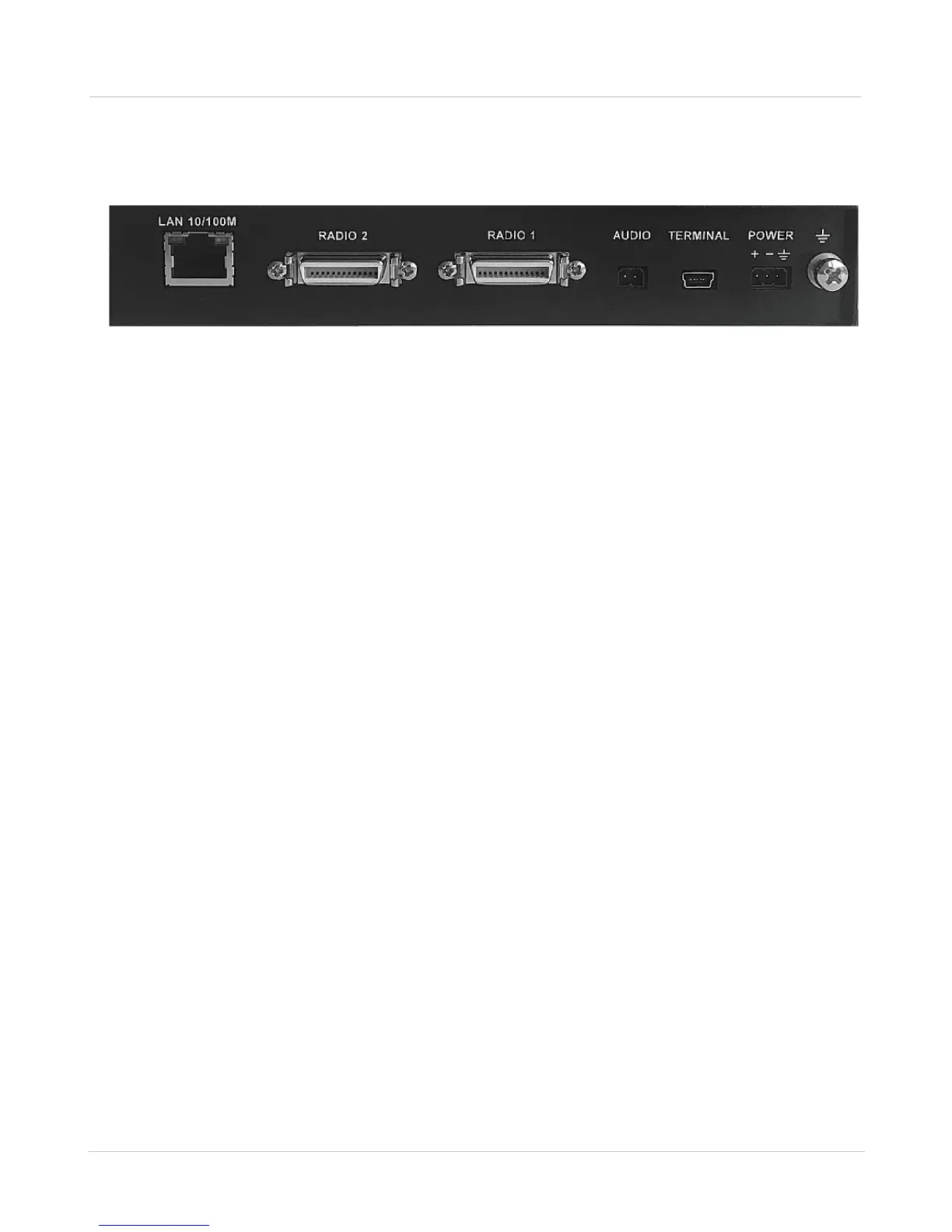
The rear panel of the RG-1000e GATEWAY is presented in the figure below.
Fig. 8 Rear panel of the RG-1000e GATEWAY
In this figure, the following nomenclature applies:
LAN (10/100): Ethernet socket for connection to the IP network. The LAN socket has green and yellow
indicators with the following possible statuses:
· Indicator is off—connection with a network device is not established.
· Green indicator is on or flashing—connection with a network device is established.
· Yellow indicator is on—the duplex mode is active.
· Yellow indicator is off—the half-duplex mode is active.
RADIO 1: Socket for the 1st Radio. The pin numbering is provided in Appendix I.
RADIO 2: Socket for the 2nd Radio. The pin numbering is provided in Appendix I.
TERMINAL: USB Mini Type-B socket for configuring the RG-1000e GATEWAY.
POWER: 11-15 VDC RG-1000e GATEWAY's power socket.
GND M4 screw, Ground.
4.3 Installation and operation check
Before installing the RG-1000e GATEWAY, it is required to perform a visual inspection of the delivery set in order
to detect the mechanical damages of the casing or connection elements. Before connecting
a radio, it is required to preset the RG-1000e GATEWAY interface. When connecting a radio, use the interface
cable from the delivery set only.
RG-1000e GATEWAY can be placed on its rubber feet or can be attached to any vertical or horizontal surfaces.
For rigid attachment of the RG-1000e GATEWAY to the surfaces, use the brackets from the
delivery set. A radio may be fixed on the upper housing cover with the use of a standard radio bracket.