19
4.3 Installation and operation check
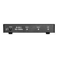
User GuideRG-1000e Remote Gateway
The external parts, that are fastened to the RG-1000e GATEWAY casing, must be attached to the RG-1000e
GATEWAY with the screws from the delivery set only. Longer screws may damage the board or its elements. The
areas of mounting the clamping elements to the RG-1000e GATEWAY casing are provided in Appendix II.
To configuration and operation check, perform the following steps:
1. Make sure the RG-1000e GATEWAY is powered down (POWER button on the front panel should be
unpressed) and the RG-1000e GATEWAY is unplugged from any devices.
2. RG-1000e may get power in 3 different ways.
Attention!!! Decide carefully how RG-1000e will get power:
· via Power socket
· via Radio1 socket or Radio2 socket
· via both Radio1 and Radio2 sockets
There are some tips which help you to deliver power properly:
· if only one Mototrbo radio is connected to the RG-1000e it is better to get power from a connected
Mototrbo radio. KM300-DM46 radio connection cable contains necessary wires for delivering power to
connected RG-1000e. Just connect the RG-1000e to the Mototrbo radio using cable KM300-DM46.
· if two Mototrbo control stations are connected to the RG-1000e you may get power from both
connected Mototrbo. In this case it is strongly recommended to use a shared DC power supply for
both connected Mototrbo radios. 13.8 VDC power supply with 30A current load is sufficient for this
task.
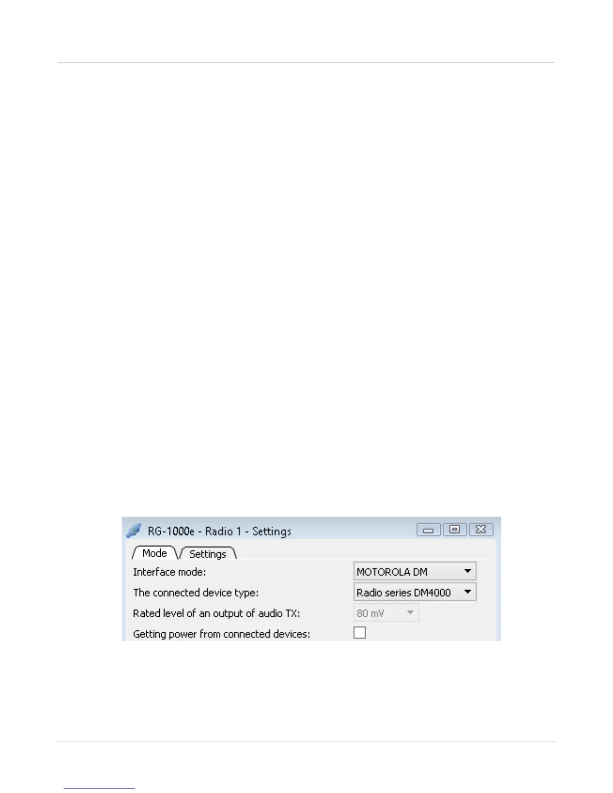
· Option "getting power from connected devices" may be turn-ON and turn-OFF by changing RG-1000e
software settings. Factory default setting is ON. You may disable this option using CPS RG-1000e,
open and change Radio1 or Radio2 settings (see the figure below). If option "getting power from
connected devices" is OFF on both Radio1 and Radio2 ports RG-1000e may get power only via Power
socket. So, before turning-OFF this option you should deliver power to RG-1000e via Power socket.
Fig. 9 Disable getting power from a connected device