20
4.3 Installation and operation check
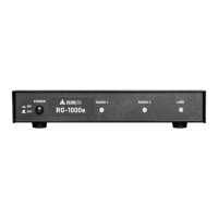
User GuideRG-1000e Remote Gateway
Attention!!! If RG-1000e and Mototrbo radios get power from independent power supply units the
negative leads of all power supply units must be connected together using the copper wire of at least 2
mm2 section !!!
3. Connect 12-14 VDC power supply to the RG-1000e GATEWAY. Connect the positive lead (+) of your power
supply with +V gateway power socket pin, the negative lead (-) of the power supply—with -V gateway power
socket pin. Recommended power cable diameter is 4-7 mm. GND pin of the gateway's power socket is connected
to the casing and the ground protection of the USB interface and LAN interface.
The picture below shows how conductors/wires should be stripped and released from the power plug.