21
4.3 Installation and operation check
User GuideRG-1000e Remote Gateway
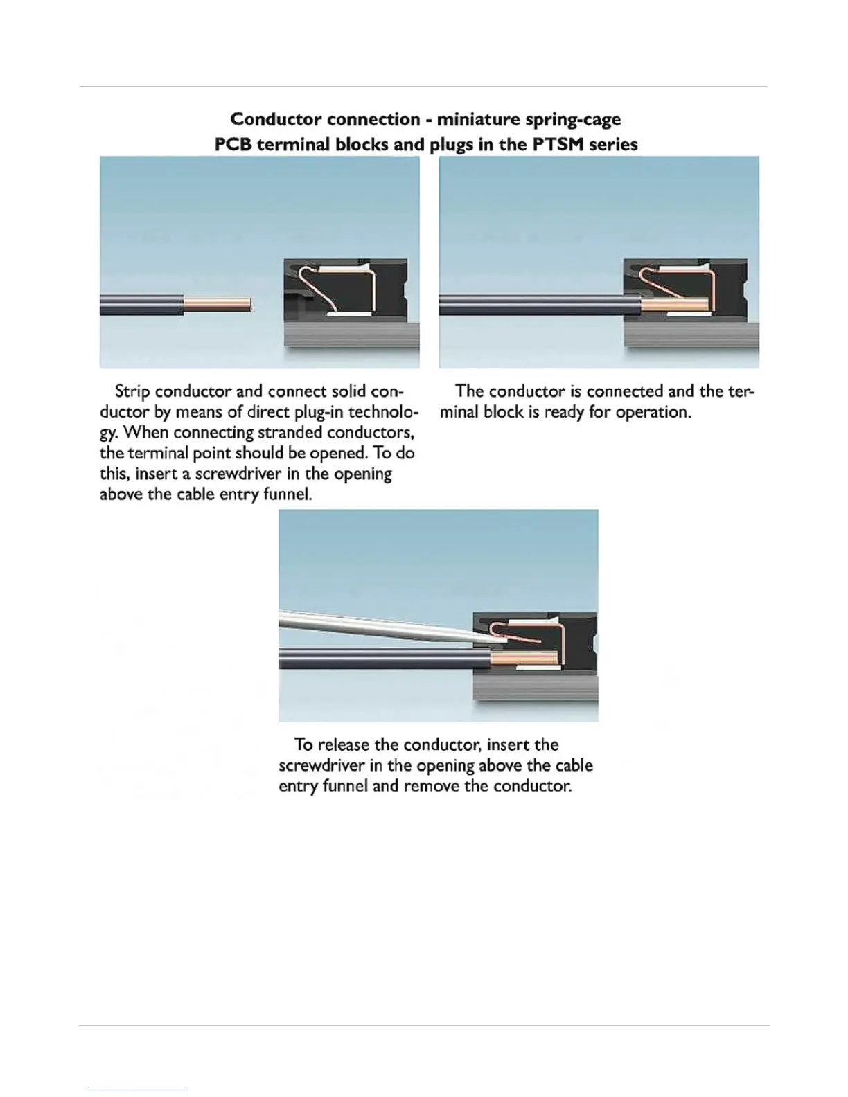
Fig. 10 RG-1000e power plug conductors connect-release
Note: The GND screw or GND pin (on the power socket) of the RG-1000e GATEWAY must be connected
to the protective ground of the facility where it is mounted !!!
Note: 15.5VDC is the maximum supply voltage for the RG-1000e GATEWAY. Don't exceed it !!!
4. Turn on the RG-1000e GATEWAY's power supply.