16
User GuideRG-1000e Remote Gateway
The IP channel connection in the RG-1000e GATEWAYs can be established in the following ways:
· Dynamically, in this case all IP channels have the same IP addresses and port numbers. Under these
parameters, connection of the radioservers is performed serially on an idle IP channel.
· Statically, in this case each IP channel has an individual IP address and/or port number (as it is shown in the
figure below).
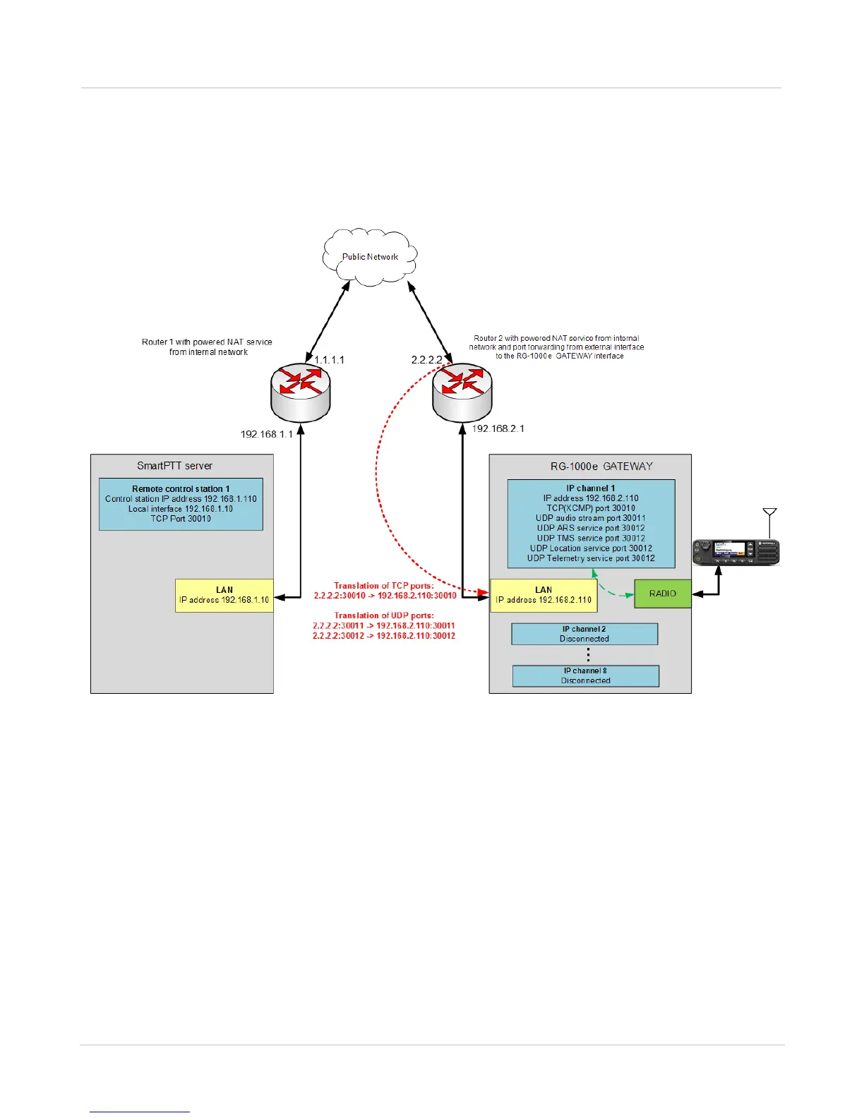
Fig. 6 Connection of the radioserver and RG-1000e GATEWAY via the network with NAT
To operate via a public network (for example, the Internet) with the address transmission on adjacent routers, the
external interface of router 2 must have a static IP address in the gateway network while the external interface of
router 1 can have a dynamic IP address in the gateway network. In the example in the figure above, router 1, the
radioserver default gateway, has the 192.168.1.1 IP address of the internal network interface and the 1.1.1.1 IP
address of the external network interface. Router 2, the default gateway of the RG-1000e GATEWAY, has the
192.168.2.1 IP address of the internal network interface and the 2.2.2.2 IP address of the external network
interface.
The radioserver and gateway are assigned the 192.168.1.10 and 192.168.2.110 static IP addresses, respectively.
The NAT Overload (Port Address Translation) service is configured on each router. Additionally, you must
configure the rules on router 2 allowing the transmission of the TCP and UDP packets with its port numbers
arriving from the external network. These port numbers are used in the settings of the gateway to its internal IP
address, in this example it is 192.168.2.110.