27
Route the cable across the back of the K3. When the KRX3A module is installed, it will connect to the
KRX3A at a point directly in front of the KIO3 board in the left rear side of the K3. If you have the KPA3 100
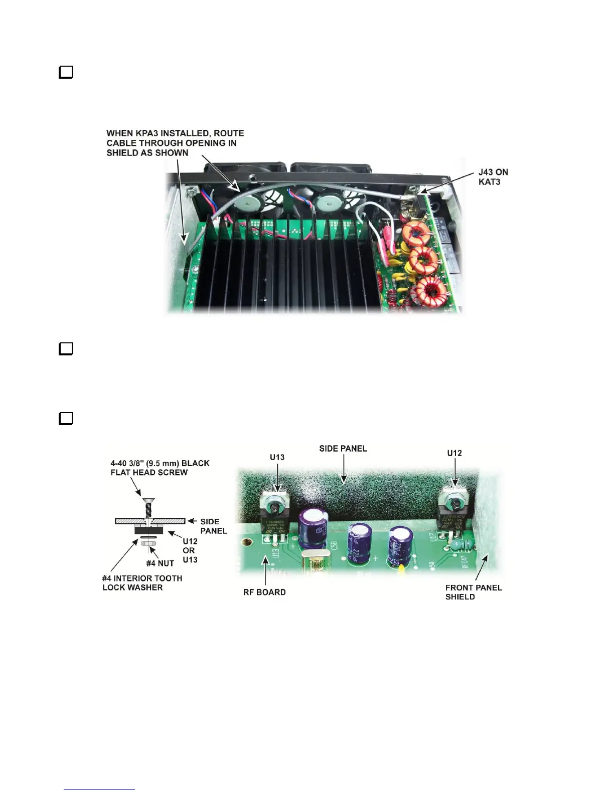
watt option installed, route the cable between the fans and heat shield and out through the hole in the KPA3
shield as shown in Figure 29. The loose end will be connected later.
Figure 29. Optional KRX3A Antenna TMP Cable to KAT3.
Go directly to Assembling the KRX3A Sub receiver Module on page 31 to continue with the installation.
Installing the Auxiliary KRX3A Antenna Input Via the Rear Panel BNC Connector
With this option the KRX3A Auxiliary Antenna input is routed to a BNC connector on the K3 rear panel.
Remove the hardware securing the heat sinks of U13 and U12 to the right side panel (see Figure 30). Be
careful not to lose the lock washers inside the K3.
Figure 30. U12 and U13 Hardware.