31
Replace the 4-40, 3/16” (4.8 mm) black flat head screw that secures the back panel to the 2D fastener as
shown in Figure 31.
Replace the two 4-40 3/8” (9.6 mm) black flat head screws, lock washers and nuts to secure the heat sinks
of U13 and U12 to the side panel as shown in Figure 30.
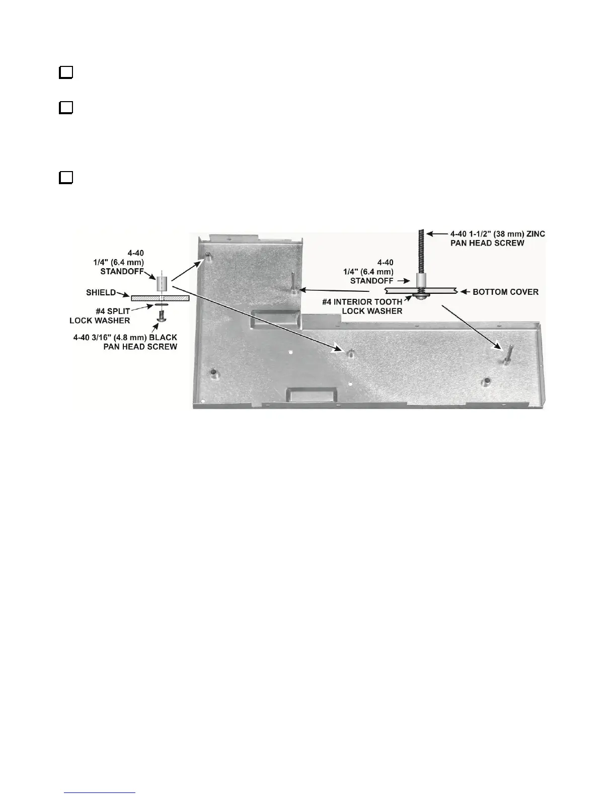
Assembling the KRX3A Sub receiver Module
Install four standoffs on the bottom half of the KRX3A shield assembly as shown in Figure 36. The bottom
of the shield has the shorter permanently mounted standoffs. The standoffs you install go on the same side of the
shield as the permanent standoffs. There are extra holes in the shield. Be sure you put the standoffs in the correct
locations and that the standoffs with the long screws are in the positions shown.
Figure 36. Mounting Standoffs on Shield Bottom.