44
If your K3 is equipped with the K144XV 2-meter option, refer to the K144XV manual to reconnect the
cables and remount the module on the left side panel. Route the power wire as shown in the K144XV manual so
it won’t be trapped between the speaker pad and the top of the KRX3A module. .
Replace the chassis stiffener bar using two 4-40 3/16” (4.8 mm) black flat head screws at the ends. If the
KPA3 is installed, attach the stiffener to the shield using two 4-40 1/4” (6.4 mm) screws with lock washers
under the screws (see Figure 3). Some stiffener bars do not have threaded PEM nuts attached. In that case,
secure the screws with the 4-40 nuts and lock washers that you removed.
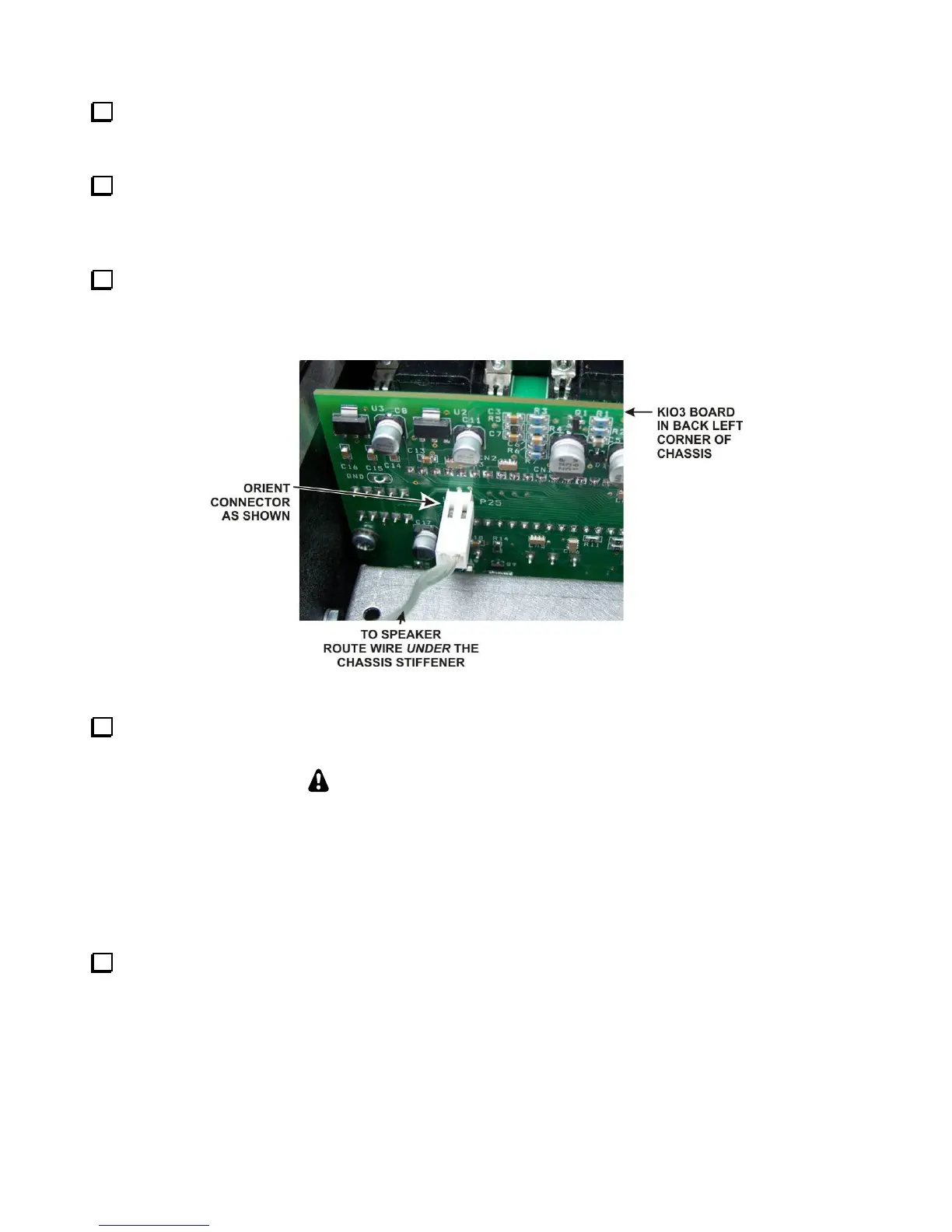
Hold the top cover above the K3, route the speaker wire under the stiffener bar and plug it into P25 on the
KIO3 board at the left rear of the K3 as shown in Figure 53. If you have the K144XV 2-meter module installed,
there is an indentation in the top of the module where you can pass the speaker wire connector under the chassis
stiffener.
Figure 53. Connecting Speaker Cable.
Position the top cover on the K3. Note that the tab on the back center goes under the rear lip of the K3 rear
panel. Secure the top cover with the nine 4-40 3/16” (4.8 mm) black flat head screws you removed earlier.
REPLACE ALL THE SCREWS!
The chassis has excellent rigidity despite its light weight. The screws that hold the top cover
in place are an important part of the structural design. Please be sure to replace all the
screws and verify they are tight whenever you replace the cover or other panels.
If you installed the optional AUX IN antenna connector on the rear panel, check to be sure
you replaced and tightened all the screws in the right side pane including the heat sink
screws for U12 and U13 and the top screw on the rear panel above the ANT connectors.
Turn to page 46 and perform the steps under Preparing for Operation. Your KRX3A sub receiver will
not operate correctly until you complete all the steps.