OUTPUT VOLTAGE CONFIGURATION
The power ampli er’s output voltage is factory pre-set to the corresponding voltage setting for
loudspeaker networks as they are usually used in the speci c country of shipment. Changing this setting
takes only little effort.
Opening the appliance is necessary to recon gure the output voltage setting.
Therefore, only trained personnel may perform recon guration.
Before changing the con guration the power ampli er has to be separated from the
mains through pulling the mains plug.
For recon guring the output voltage, please proceed as follows:
For the RCM-24 Module to be able to assign the corresponding currents and voltages, the appliance
needs to be modi ed as follows:
- Remove all screws securing the cover plate.
- Remove the plastic screw in the top plate.
- Open the appliance by removing the cover.
- On the printed board assembly 86276:
for 100V output voltage: close the bridge R56
for 70V output voltage: open the bridge R56
- Proceed in reverse order to reassemble the appliance.
The ground-lift switch allows eliminating noise loops. If the power ampli er
is operated together with other equipment in a 19“ rack-shelf, setting the
switch to its GROUNDED position is recommended. If the power ampli er
is operated together with appliances with differing ground potentials, setting
the switch to its UNGROUNDED position is recommended
Under normal circumstances, the mains fuse only blows in case of fault.
Replacing the fuse is only permissible when using a new fuse of the same
type with identical amperage, voltage and blow characteristics. If the mains
fuse blows more often, please contact an authorized service centre.
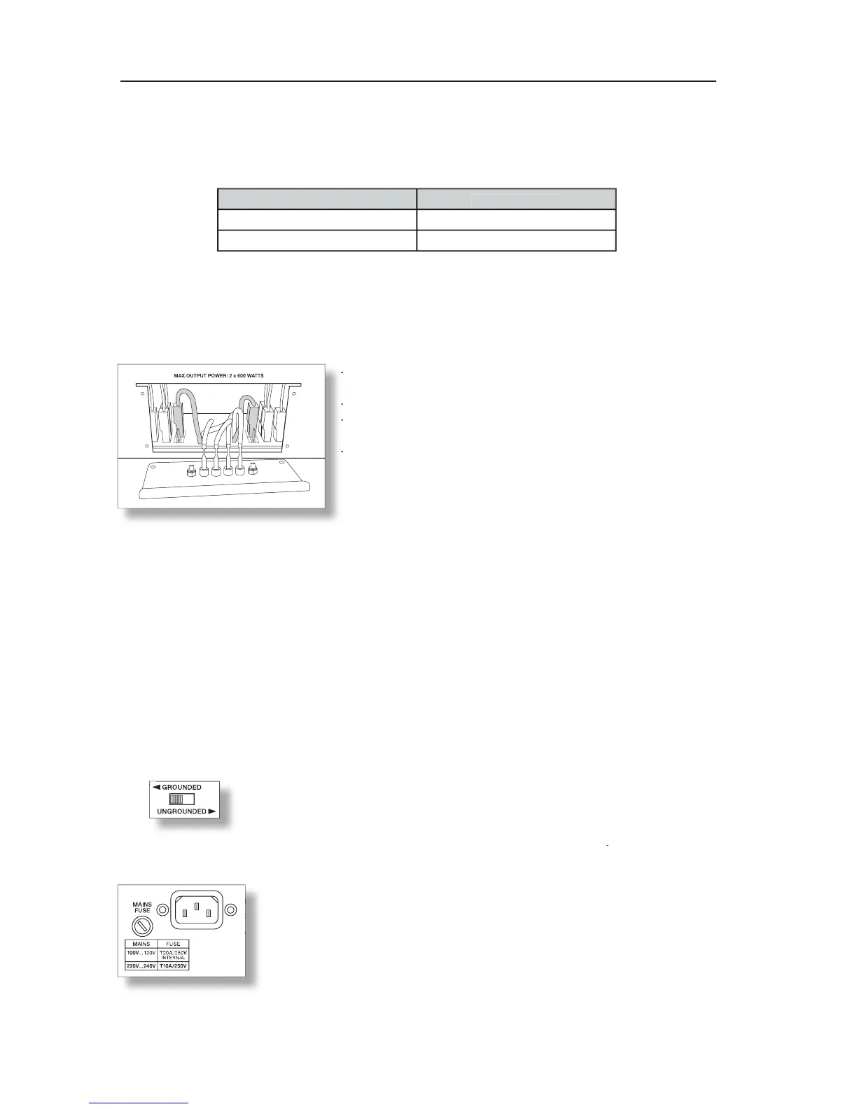
- Disconnect any cables connected to the appliance; especially
- Disconnect any cables connected to the appliance; especially
- Remove all xing screws of the output connectors panel.
- Remove all xing screws of the output connectors panel.
- Pull out the panel by holding it at the terminal strips
- Pull out the panel by holding it at the terminal strips
- The connector pins 100V and 70V are for selecting the desired
- The connector pins 100V and 70V are for selecting the desired
output voltage for channel A (right channel) & B (left channel).
output voltage for channel A (right channel) & B (left channel).
- Change the output voltage by pulling the corresponding
connector (grey shaded in the diagram) and inserting it to the
connector (grey shaded in the diagram) and inserting it to the
connector pin for the desired voltage setting.
connector pin for the desired voltage setting.
- The diagram shows the con guration with both channels set