The CAN-bus allows using different data rates, with the data
rate being indirectly proportional to the bus length. Small net
works allow baud rates up to 500kbit/s.
For sizable dimensioned networks reducing the baud rate
(minimum 10kbit/s) is necessary. The integration of
repeaters is generally recommended when the bus-length
CAN-BUS CABLE SPECIFICATIONS
According to the ISO 11898-2 standard, CAN-bus data transfer cabling has to be carried out using
Twisted-Pair cables with or without shielding providing a characteristic impedance of 120
a CAN-bus need to be terminated with 120
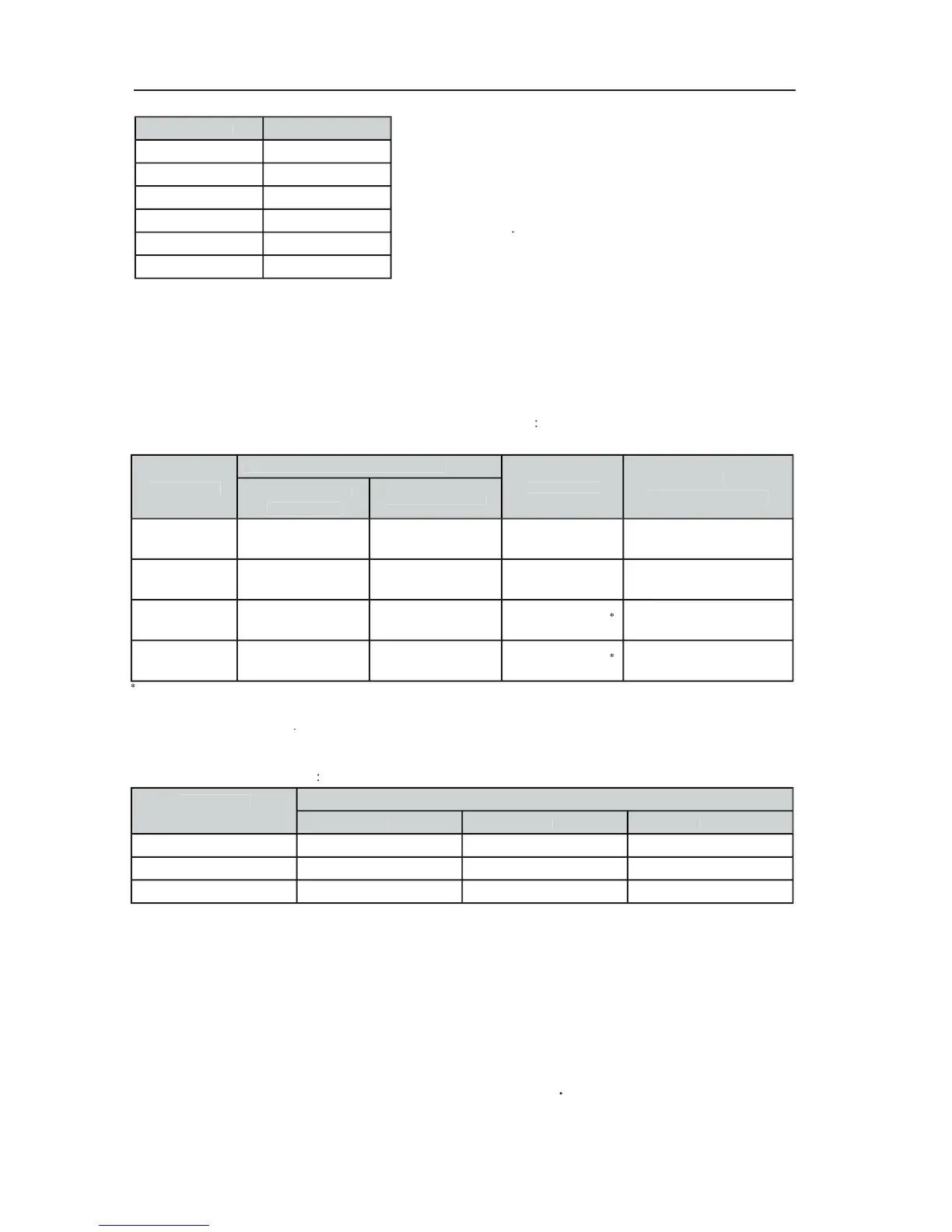
The maximum bus-length depends on the actual data transfer rate, the kind of data transfer cable being
used, as well as the total number of participants on the bus. The following table shows the most essential
coherencies for CAN-networks consisting of up 64 participants
Cable for data Transmission
With longer cables and many participants on the CAN-bus, termination resistors with higher impedance than the
are recommended to reduce the ohmic load of the interface drivers and therefore the voltage drop
between the two cable ends
The following table is meant for rst assessment of necessary cable diameters for different bus lengths
and bus-participant numbers
Number of Appliances on the CAN-Bus
Additionally, the length of branch lines – for participants that are not directly connected to the CAN-bus
– is also of importance. For data transfer rates of up to 125kbit/s, the maximum length of a single stub
cable should not exceed 2m. For higher bit rates a maximum length of only 0.3m is still permissible. The
entire length of all branch lines should not exceed 30 m.
As long as only short distances (up to 10m) are concerned, common RJ-45 patch cables with
characteristic impedance (AWG 24 / AWG 26) can be used for the cabling inside of a rack-
shelf system. The previously outlined guidelines for network cabling are mandatory as far as the
rack-shelve interconnection or xed installations are involved