6
ARCHIMEDE LCD SERIES - ENG
ELECTROIL
5.
ASSEMBLING AND INSTALLATION
Read this manual and the motor pump
one before device installation.
If the product shows clear damage signs,
do not install it, but contact the assistant
service.
Respect working limits and be careful about the motor and
inverter’s cooling. Follow safety and accident-prevention rules
carefully.
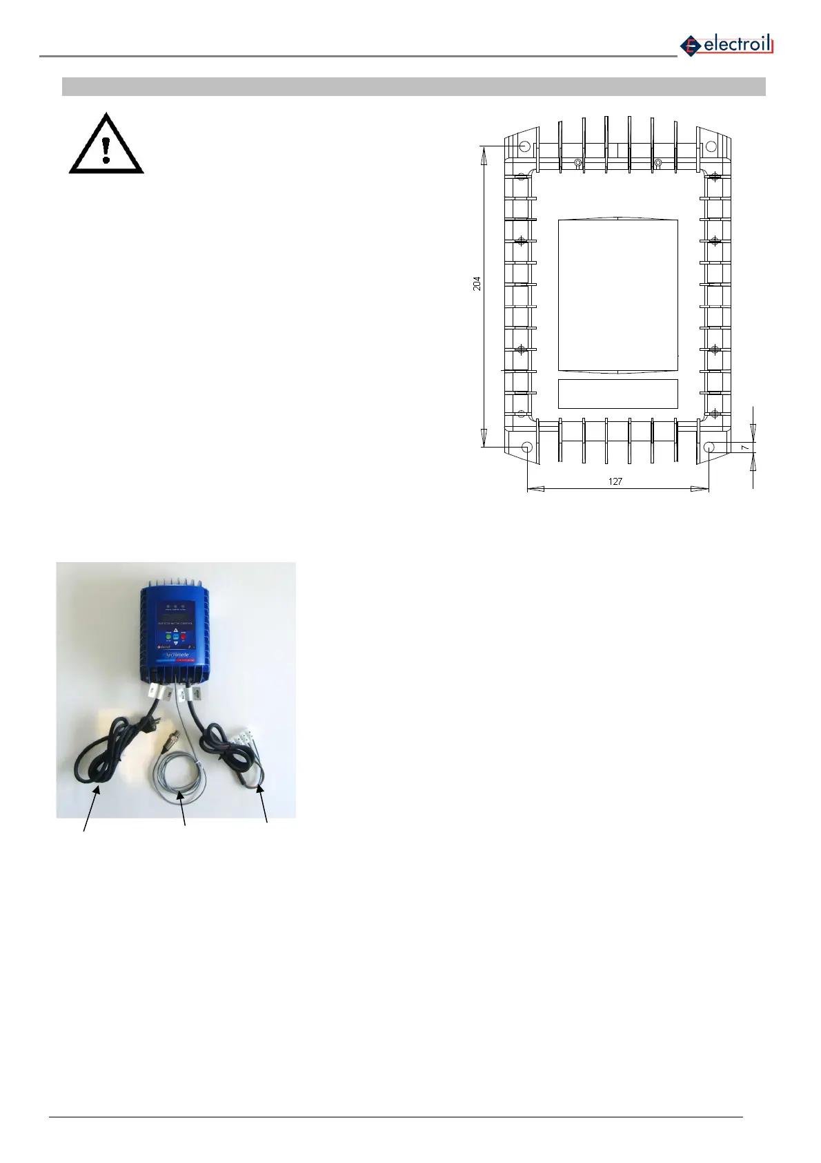
5.1 Fixing measures
Install the product in place away from frost and weather
conditions, mounting the unit on a wall in a vertical position
only, leaving at least 200mm of space above and below the
same so as to ensure sufficient cooling of the heat sink on
the back of the inverter. The wall may also be of metal type
as long as it is not a heat source and be not directly exposed
to the sun.
For wall mounting the inverter using the N° 4 holes 7mm
diameter arranged in the pattern of holes in Figure 3.
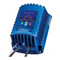
5.2 Electric and hydraulic connections
Connect the input voltage supply cable to the electric line (N°1, fig. 4); for
single phase input the standard plug is schuko type.
To control pressure in feedback you need to connect to the pump outlet, the
pressure transducer supplied (No. 2 fig 4), ¼ "M, coming from the central of
the inverter.
Connect the motor supply cable to the asynchronous three-phase motor of
the pump (N°3, fig.4)
The type of transducer supplied may be a different one presented in this
handbook, but maintaining the same connection and functioning.
Figure 3: Fixing holes distances (millimetres)
Fig. 4: Input/output and pressure transducer connections
1) Inverter
voltage supply
2) Pressure
transducer
3) Motor pump cable