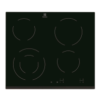
SOI 04.05 FV 35/57 599 36 62-62
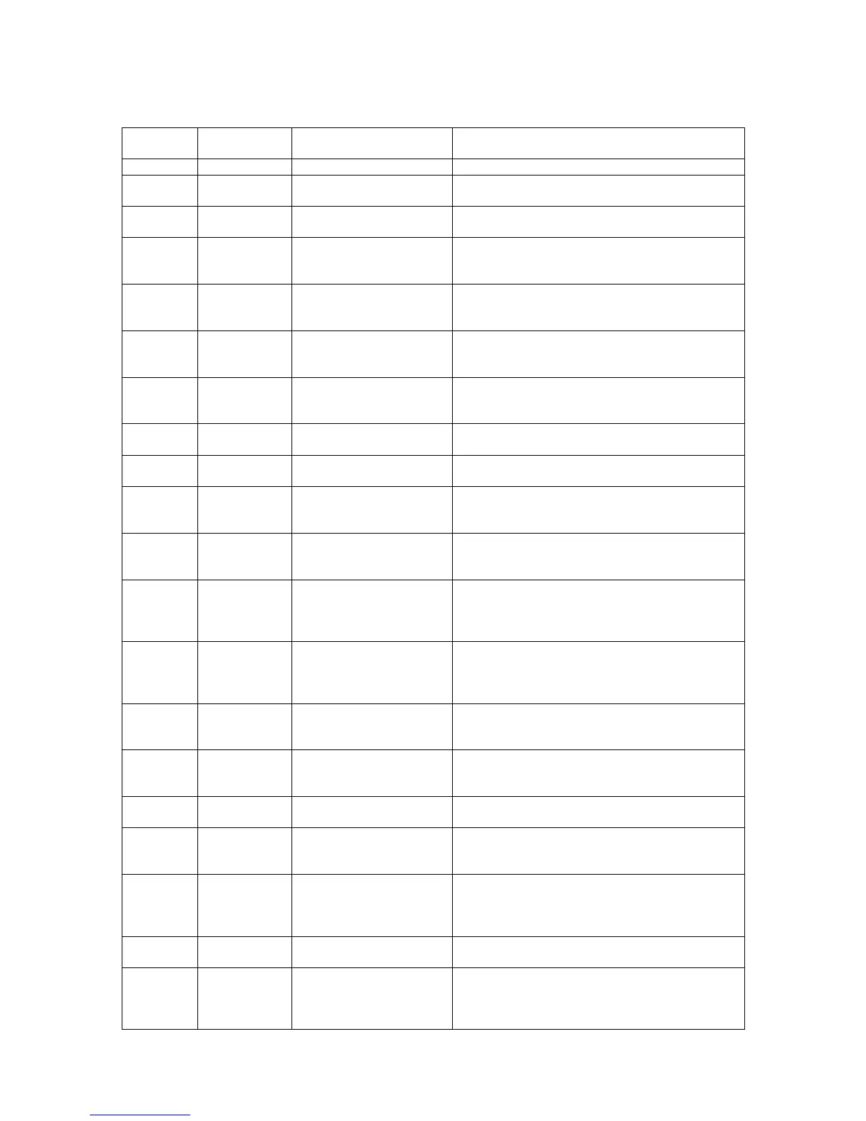
The table below lists the various error codes with their meanings.
ERROR
COSE
BLOCK ERROR CODE
DESCRIPTION
CAUSE
0
--
NO ERROR
Normal condition for an operating burner.
1
BURNER
NO FLAME AFTER RETRY
Condition of the burner after 3 consecutive
attempts of failed switching on.
2
BURNER
EV F
EEDBACK FAULT
Condition of the burner in case of “solenoid
valve feedback” wrong.
3
BURNER
SM P
HASE 1 FAULT
Condition of the burner in case of error signal
referring to the relative valve (wrong contacts
on the cables).
4
BURNER
SM P
HASE 2 FAULT
Condition of the burner in case of error signal
referring to the relative valve (wrong contacts
on the cables).
5
BURNER
SM P
HASE 3 FAULT
Condition of the burner in case of error signal
referring to the relative valve (wrong contacts
on the cables).
6
BURNER
SM P
HASE 4 FAULT
Condition of the burner in case of error signal
referring to the relative valve (wrong contacts
on the cables).
7
BURNER
SM E
NABLE FAULT
Condition of the burner in case of global error
signal or referred to more simultaneous errors.
8
BURNER
G
ENERIC FAULT
Generic error condition of the burner in case
the cause does not have a specific code.
9
SYSTEM
TEMPERATURE OUT OF
R
ANGE FAULT
Condition of the burner in case the
temperature detected on the power board
exceeds 105°C.
10
BURNER
C
ONTINUOUS RUN
Condition of the burner in case of continuous
operation longer than 4 hours without any
alteration of the flame level.
11
SYSTEM
POWER SUPPLY VPP
FAULT
Condition of the burner in case the ratio
between the supply values on the power board
is not correct.
(12,8 V and 5 V).
12
SYSTEM
POWER SUPPLY VDD
F
AULT
Condition of the burner in case the ratio
between the supply values on the power board
is not correct.
( 3,3 V e 5 V).
14
BURNER
A
BNORMAL TC
C
ONDITION
Condition of the burner in case of anomalous
flame (parasite flame, incorrect thermocouple
signal).
15
SYSTEM
SYSTEM LOCKEED FATAL
FAULT
Condition of double error on a burner valve on
all burners (internal controls to the system
regarding the different error signals).
16
SYSTEM
NTC SENSOR FAULT
Condition of each burner in case of incorrect
temperature detection on the power board.
17
SYSTEM
TIME BASE RATIO FAULT
Condition of each burner in case the internal
clock frequency ration is incorrect (32 kHz and
8MHz).
18
SYSTEM
AD CONVERTER FAULT
Condition of each burner in case the valve
control is incorrect (the “ADConverter” on the
power board does not give the requested
measurement).
19
SYSTEM
DATA MEMORY FAULT
Condition of each burner in case an error in
RAM on the power board is detected.
20
SYSTEM
PROGRAM
C
ONFIGURATION MEMORY
F
AULT
Condition of each burner in case an error in
ROM on the power board is detected.