110
Page
Poly Pro to Poly Pro flue connection
Verify gasket is sitting correctly.
Apply a light soapy water film to the gasket and tube end.
Insert pipe fully into end fitting, Pipe will push in smoothly
and evenly, should this not occur remove pipe and reset
gasket. Reapply light soapy film to ensure easy fit.
Rotate clip so catch is opposite the location tab
Clip catch into place to prevent flue pipes from separating.
Ensure pipes are clipped adequately.
Ensure a minimum of 3deg fall occurs towards the drain
end.
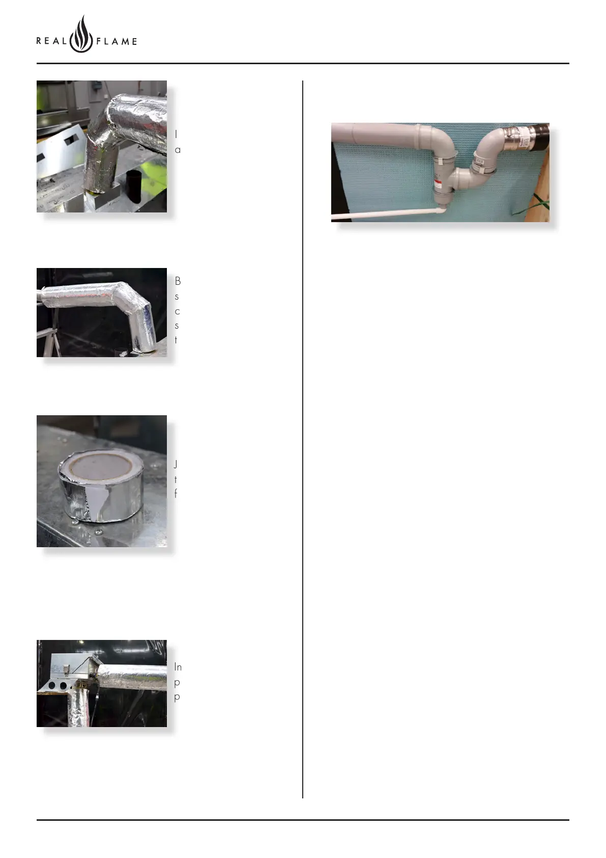
Condensate drain - P trap fitting
NOTE – DRAINAGE MUST FALL TOWARDS
CONDENSATE TRAP LOCATED AT THE END OF THE
ALUMINUM FLUE SECTION
A P-TRAP MUST BE INSTALLED AS SHOWN
Connect 90deg elbow to Aluminum adapter facing
downwards
Connect 2nd 90deg Elbow to first.
Connect vertical condensate tee to elbow with drain at
bottom.
Connect drain cap to bottom of condensate tee.
Connect flue as required to rooftop termination.
P trap must be lowest part of the Polyflue system.
All poly flue must drain back to the P trap.
Connect waste pipe to p trap (PVC pressure pipe glue
will be required for the connection.)
Insulation to be fully closed
and sealed along length.
Bends were practical
should be insulated, by
cutting the insulation into
segments and taping
together.
Joins can be taped
together using aluminum
foil self adhesive tape.
Insulation may be fitted
prior and after the inline
powerflue fan.
Failure to fit insulation on the exhaust flue may result in
condensation failures with the appliance.
Insulation to be run for the first 3m from the appliance. For
flue runs shorter than 3m, insulation is not required.