33
Page
Setup with internal fan module with wall
termination – appliance mounted
Maximum 5m flue length
Wall termination
1. Wall terminal must be installed with clearances as
specified by AS5601.1-2013 Clause 6.9.3
2. Run exhaust flue and air intake flue as required –
Maximum run 3m per flue. Flues can be run next to
each other. Maintain clearances to combustibles.
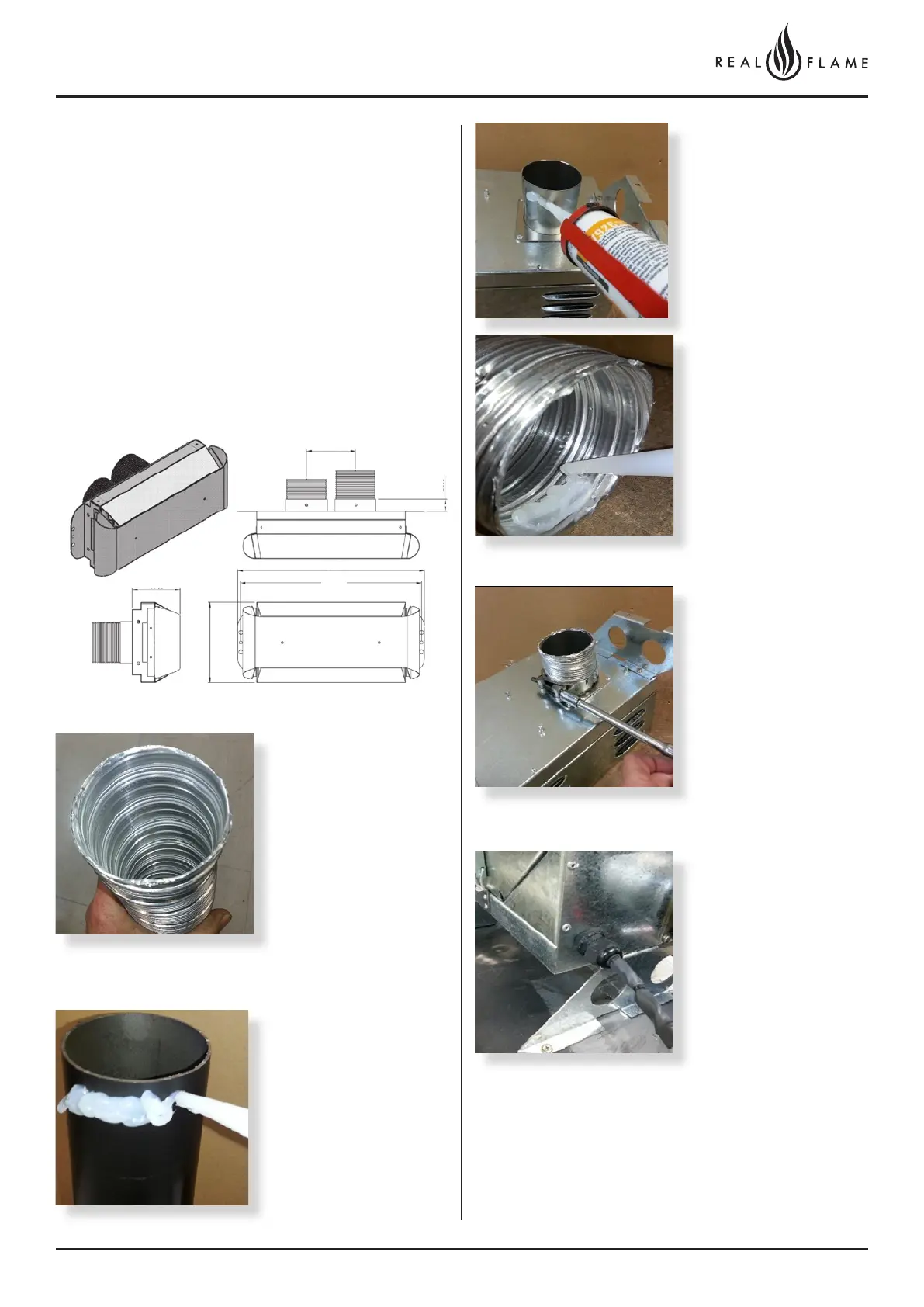
3. Connection to appliance
Check 75mm flue piece
for correct shape and
fitment onto appliance
spigot.
Ensure ends are burr free
and round, test fit flue will
slide over the connection.
Recommended Silicon
– Non-acetic, neutral
cure 150degc or higher
temperature rated.
Bostik RTV 926 or similar.
Apply an 8mm thick silicon
bead fully around heater
connection approx. 10mm
from the top.
Apply an 8mm silicon
bead fully around the
inside of the flue end, both
ends.
Apply an 8mm thick
silicon bead fully around
the lower fan connection
spigot approx. 10mm from
the end.
Turn fan assembly upside
down and slide 65mm flue
section fully onto spigot.
Fit flue clamp and tighten
clamp fully.
Wipe excess silicon,
visually check connection
to ensure connection is
fully sealed.
(Note 90° left connection is
not available and must be done
using the 90° right connection
fan location and placing a
bend in the flue to head in the
LH direction.
Fit 2nd flue clamp loosely
onto the 65mm section of
flue.
Lift fan assembly into
appliance and locate onto
flue connection. Insert fully.
Locate fan in the required
direction. Screw fan
assembly down onto
the appliance. (Screws
prefitted into holes are
located on the appliance
for direct out back
connection and 90° to
right connection.)
100
383
97
371
25
164