56
Page
Locate wall mounting
bracket into position and
affix to wall.
Feed power cable through
bottom area of bracket.
Assemble spigot
connection plate assembly
to wall mounting bracket.
(4 screws)
Assemble main body
assembly onto wall
mounting bracket, feed
power cable through
grommet hole prior to
fitting. (refit 5 screws
as shown and tighten)
Main body assembly
must sit flush up against
the mounting bracket and
seal.
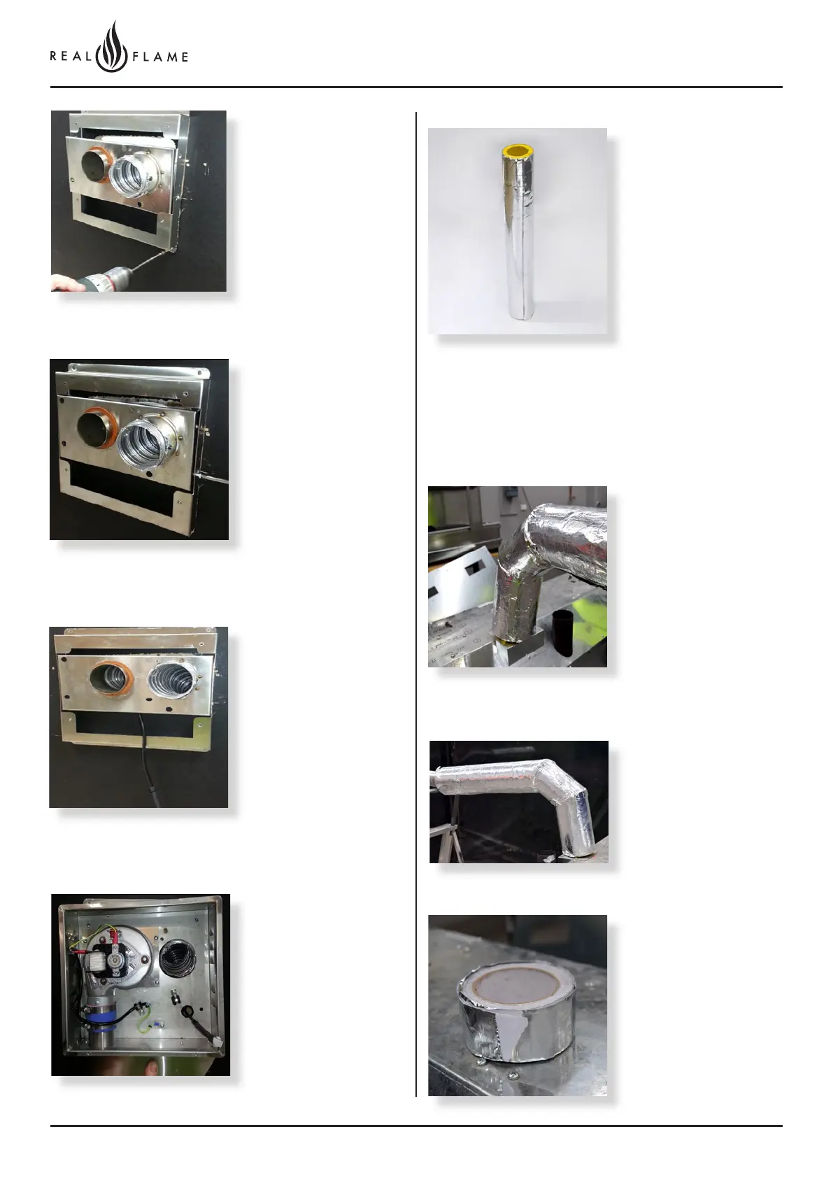
Insulation must start as close to the gas space heater as
possible
(Only exhaust flue is to be insulated)
Insulation to be fully closed
and sealed along length.
Bends were practical
should be insulated, by
cutting the insulation into
segments and taping
together.
Fit flue exhaust insulation
Insulated with 25mm foil
faces glasswool pipe
insulation, as supplied by
Glen Dimplex Australia.
Joins can be taped
together using aluminum
foil self adhesive tape.