59
Page
Setup with internal fan module with wall
termination – appliance mounted
Maximum 9m flue length
Wall termination
1. Wall terminal must be installed with clearances as
specified by AS5601.1-2013 Clause 6.9.3
2. Run exhaust flue and air intake flue as required –
Maximum run 9m per flue. Flues can be run next to
each other. Maintain clearances to combustibles.
3. Insulation Instructions-
Exhaust flue must be insulated using 25mm glass wool
pipe insulation as supplied by Glen Dimplex Australia.
Insulation must be fitted to exhaust (hot side only).
Insulation must start as close to appliance as possible
(within 300mm).
Insulation must finish as close to discharge as possible
(within 300mm).
Insulation must run around bends.
Insulation to be taped to ensure no gaps.
Insulation may be fitted while running flue or at final
stage of installation.
(shown at flue stage in Instructions)
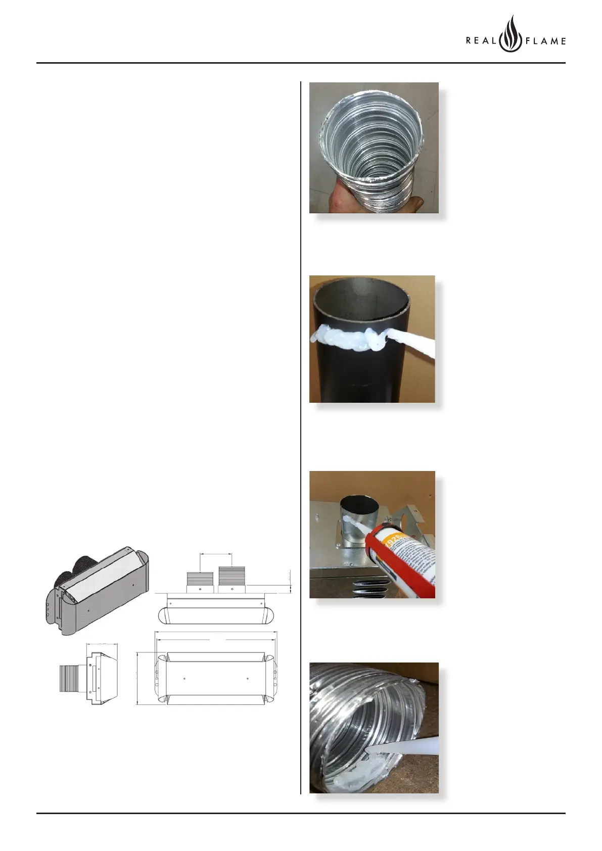
4. Connection to appliance
Check 75mm flue piece
for correct shape and
fitment onto appliance
spigot.
Ensure ends are burr free
and round, test fit flue will
slide over the connection.
Recommended Silicon
– Non-acetic, neutral
cure 150degc or higher
temperature rated.
Bostik RTV 926 or similar.
Apply an 8mm thick silicon
bead fully around heater
connection approx. 10mm
from the top.
Apply an 8mm silicon
bead fully around the
inside of the flue end, both
ends.
Apply an 8mm thick
silicon bead fully around
the lower fan connection
spigot approx. 10mm from
the end.
100
383
97
371
25
164