60
Page
Turn fan assembly upside
down and slide 65mm flue
section fully onto spigot.
Fit flue clamp and tighten
clamp fully.
Wipe excess silicon,
visually check connection
to ensure connection is
fully sealed.
(Note 90° left connection is
not available and must be done
using the 90° right connection
fan location and placing a
bend in the flue to head in the
LH direction.
Fit 2nd flue clamp loosely
onto the 65mm section of
flue.
Lift fan assembly into
appliance and locate onto
flue connection. Insert fully.
Locate fan in the required
direction. Screw fan
assembly down onto
the appliance. (Screws
prefitted into holes are
located on the appliance
for direct out back
connection and 90° to
right connection.)
Locate 2nd clamp onto lower connection and tighten
clamp fully.
Wipe excess silicon, visually check connection to ensure
connection is fully sealed.
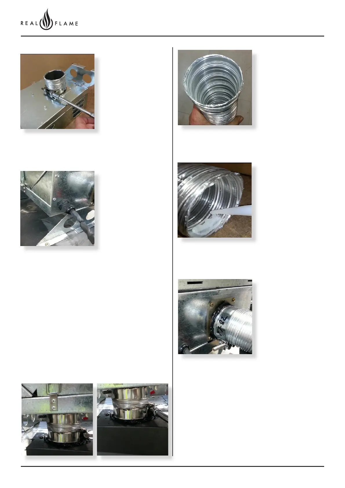
Fit hot exhaust flue pipe
from outlet termination to
fan outlet connection.
Cut tube to length where
required.
Ensure ends are burr free
and round, test fit flue will
slide over connection.
Apply an 8mm thick silicon
bead fully around heater
connection approx. 10mm
from the top.
Apply an 8mm silicon
bead fully around the
inside of the flue end
(heater connection end)
Fit flue clamp over flue
(loosely).
Slide flue onto connection
spigot fully.
Tighten clamp fully.
Wipe excess silicon,
visually check connection
to ensure connection is
fully sealed.