65
Page
5. Insulation Instructions-
Exhaust flue must be insulated using 25mm glass wool
pipe insulation as supplied by Glen Dimplex Australia.
Insulation must be fitted to exhaust (hot side only).
Insulation must start as close to appliance as possible
(within 300mm).
Insulation must finish as close to discharge as possible
(within 300mm).
Insulation must run around bends.
Insulation to be taped to ensure no gaps.
Insulation may be fitted while running flue or at final
stage of installation.
(shown at flue stage in Instructions)
Setup with internal fan module with wall
termination – mid flue mounted
Maximum 9m flue length
Wall termination
1. Wall terminal must be installed with clearances as
specified by AS5601.1-2013 Clause 6.9.3
2. Run exhaust flue and air intake flue as required –
Maximum total run 9m per flue. Flues can be run next
to each other. Maintain clearances to combustibles.
3. Mount fan controller in the required location. (Access
to the fan module is required for servicing, if the fan
module is located inside a boxed frame, allow a 450
x 450 access panel).
4. Connection to fan module to appliance run flue from
appliance to bottom entry on fan module. Support
flue with brackets as required.
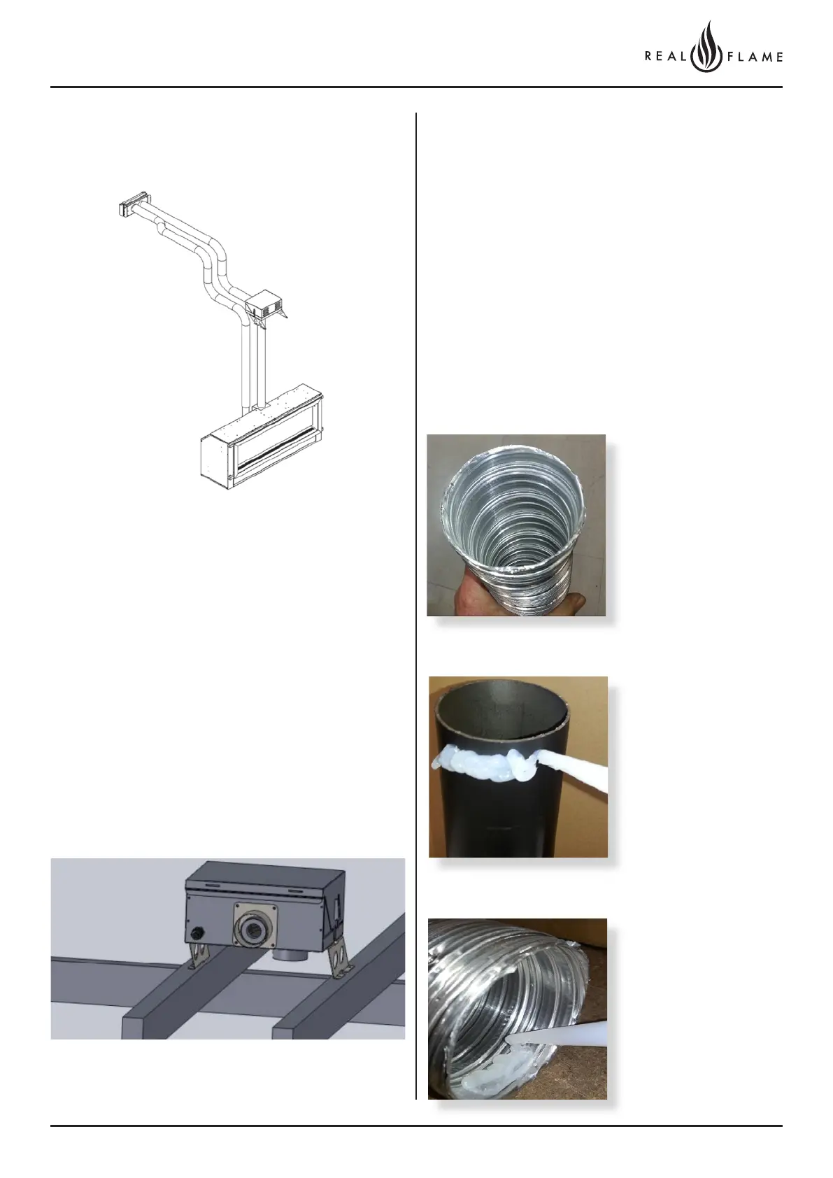
Cut tube to length where
required.
Ensure ends are burr free
and round, test fit flue will
slide over connection.
Apply an 8mm thick silicon
bead fully around heater
connection approx. 10mm
from the top.
Apply an 8mm silicon
bead fully around the
inside of the flue end
(heater connection end)
Fit flue clamp over flue
(loosely).