66
Page
Fan module outlet
connection
Cut tube to length where
required. Ensure ends
are burr free and round,
test fit flue will slide over
connection.
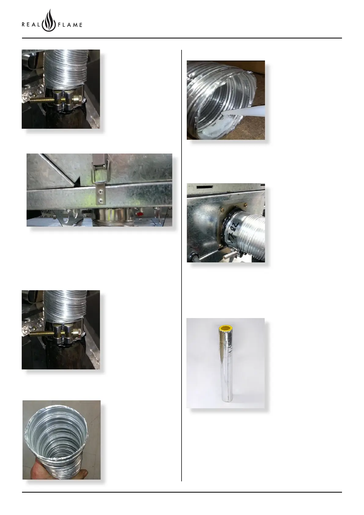
Slide flue onto connection
spigot fully.
Tighten clamp fully.
Wipe excess silicon,
visually check connection
to ensure connection is
fully sealed.
Apply an 8mm thick silicon
bead fully around heater
connection approx. 10mm
from the top.
Apply an 8mm silicon
bead fully around the
inside of the flue end
(heater connection end)
Fit flue clamp over flue
(loosely).
Repeat for air intake flue
connection.
Repeat for connection to underside of fan module.
NOTE: Flue run must be a minimum of 2m from appliance
to fan module.
Slide flue onto connection
spigot fully.
Tighten clamp fully.
Wipe excess silicon,
visually check connection
to ensure connection is
fully sealed
Insulation must start as close to the gas space heater as
possible
(Only exhaust flue is to be insulated)
Fit flue exhaust insulation
For all Element 900
installations using inline
fan configurations (where
flue length exceeds 3m),
the first 3m (or up to 3m)
of exhaust flue must be
insulated with 25mm foil
faces glasswool pipe
insulation, as supplied by
Glen Dimplex Australia.