6
Your new TV is heavy, please consult with professional
wallmount installer to perform this installation.
PREPARATIONS
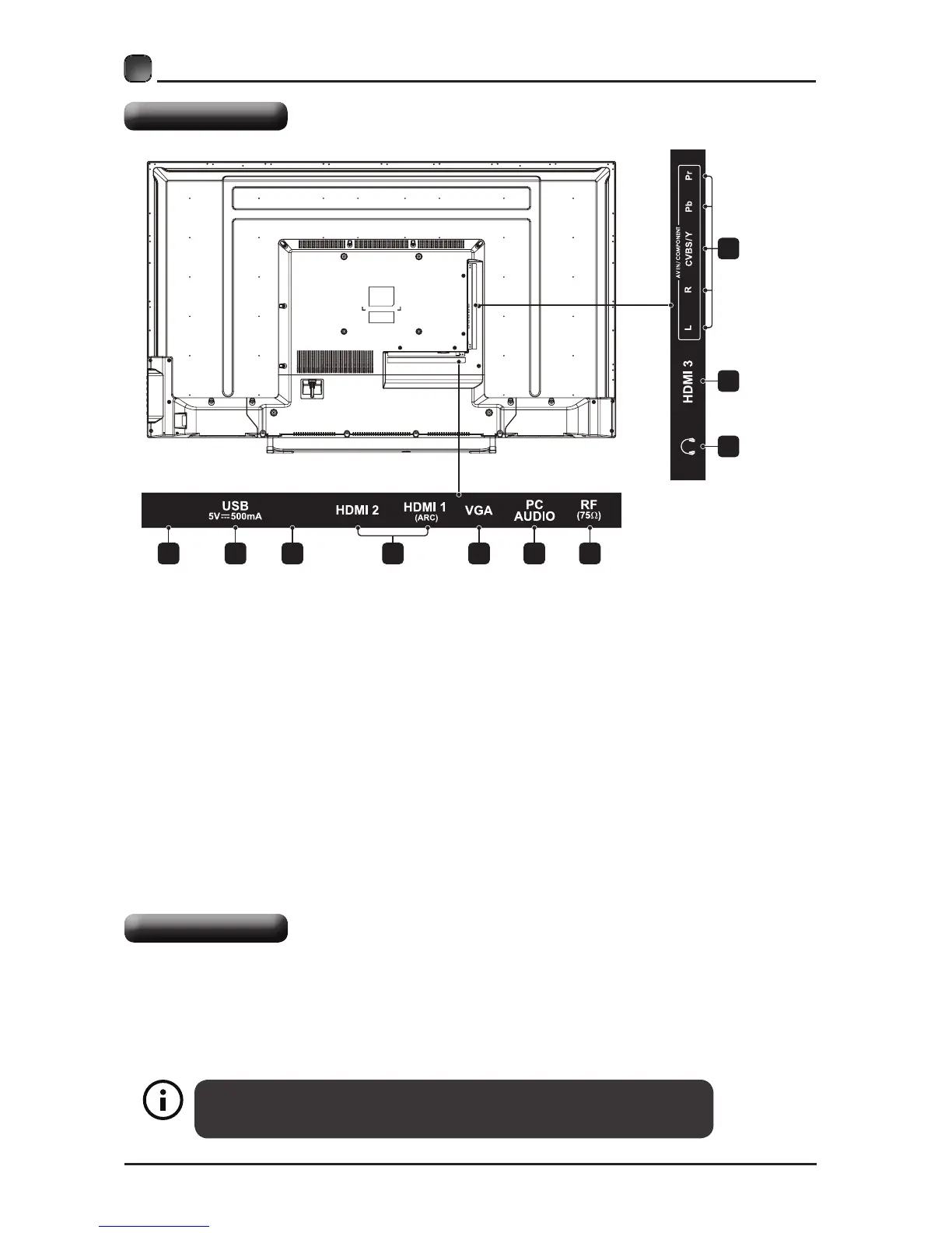
Rear View
Wall Mounting
1.Optical Output
Connect a digital sound system to this
jack.
2.USB Input
Connect to a USB storage device to play
photoles.(USBmode)
3. LAN
Network connection port.
4. HDMI Inputs
ConnecttoaHigh-Denition(HD)signal
input device.
5. VGA Input
Connect to a computer or other devices
with a VGA interface.
6. PC Audio Input
Connect to a computer audio output.
7. Antenna Input (75Ω VHF/UHF)
Connecttotheantenna(75ΩVHF/UHF)
socket with the RF coaxial cable.
8. Headphone output
Connect to the Headphones.
9. COMPONENT/AV Input
Connect to AV devices with composite/
component(Y/Pb/Pr)videoandaudio
output sockets. COMPOSITE VIDEO and
COMPONENT(Y/PB/PR)sharewithAUDIO
IN(L/R).
The TV is provided with mounting holes for a VESA approved wall mounting bracket (Not
Supplied).Removethescrewsholdingthebasetothebasebracketandliftthebaseaway
(donotremovethebasemountingbrackets).MounttheVESAbracketusing4*M6isometric
threadedscrews(NotSupplied).
LAN
OPTICAL
1
8
4
9
2 3 5 6 74