4. OPERATION MAINTENANCE
4-1 Battery and Fuse Replacement
-32-
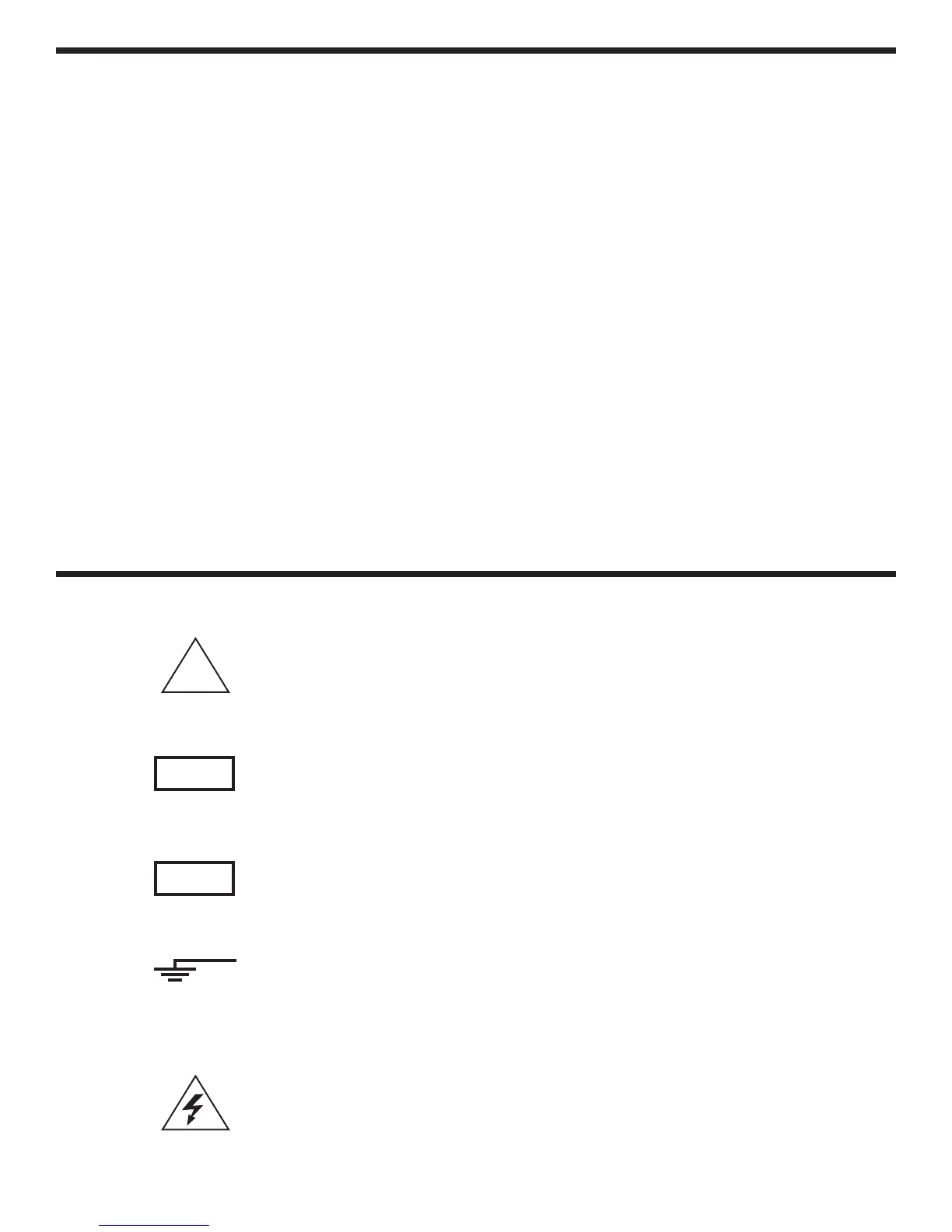
This marking adjacent to another marking or a
terminal operating device indicates that the
operator must refer to an explanation in the
operating instructions to avoid damage to the
equipment and/or to avoid personal injury.
This WARNING sign denotes a hazard. It calls
attention to a procedure, practice or the like, which
if not correctly performed or adhered to, could result
in personal injury.
This CAUTION sign denotes a hazard. It calls
attention to a procedure, practice or the like, which
if not correctly adhered to, could result in damage to
or destruction of part or all of the instrument.
This marking advises the user that the terminal(s)
so marked must not be connected to a circuit point
at which the voltage, with respect to earth ground,
exceeds (in this case) 500 volts.
This symbol adjacent to one or more terminals
identifies them as being associated with ranges that
may in normal use be subjected to particularly
hazardous voltages. For maximum safety, the
instrument and its test leads should not be handled
when these terminals are energized.
5. SAFETY SYMBOLS
CAUTION
BEFORE ATTEMPTING BATTERY REMOVAL OR
REPLACEMENT, DISCONNECT THE TEST
LEADS FROM ANY ENERGIZED CIRCUITS TO
AVOID SHOCK HAZARD.
The fuse rarely needs replacement and blow almost
always as a result of operator error. To replace the
battery and fuse (2A/250V), remove the two screws
in the bottom of the case. Simply remove the old
battery or fuse and replace with a new one.
Be sure to observe the polarity when replacing the
battery.
4-2 Calibration Procedure
It is normally not necessary to recalibrate for long
intervals. If needed, adjustment should be done
with highly accurate standards (setter than 0.1%
accuracy).
Remove the two phillips head screws. Carefully
remove the plastic back cover. With the instrument
operating and set to the 200mV DC range (20mF
capacitance range), apply 190mV DC (10mF) from
an accurate source. With a small screwdriver
inserted into the semi-fixed resistor VR1 (VR2:
Capacitance), carefully turn the variable resistor
until the reading reads 190mV (10mF).
NOTE: Be sure to proceed basic calibration by DC
range first prior to capacitance.
WARNING
CAUTION
500V max.
!
 Loading...