-4-
RESISTANCE MEASUREMENTS
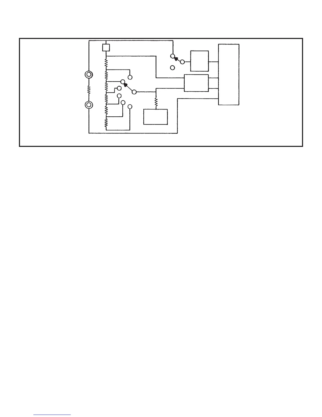
Figure 5 shows a simplified diagram of the resistance measurement function.
Figure 5 Simplified Resistance Measurement Diagram
External
Resistor
100
900
90k
900k
9M
9k
2k
200
20k
200k
2M
20M
Voltage
Source
Reference
Voltage
Low
Pass
Filter
7106R
DCW
AC CAP
A simple series circuit is formed by the voltage
source, a reference resistor from the voltage divider
(selected by range switches), and the external
unknown resistor. The ratio of the two resistors is
equal to the ratio of their respective voltage drops.
Therefore, since the value of one resistor is known,
the value of the second can be determined by using
the voltage drop across the known resistor as a
reference. This determination is made directly by
the A/D converter.
Overall operation of the A/D converter during a
resistance measurement is basically as described
earlier in this section, with one exception. The
reference voltage present during a voltage
measurement is replaced by the voltage drop
across the reference resistor. This allows the
voltage across the unknown resistor to be read
during the read period. As before, the length of the
read period is a direct indication of the value of the
unknown.
 Loading...