PART IDENTIFICATION CARDS
To help identify the resistors and diodes used in the construction of your digital
multimeter we have mounted the diodes and resistors of each section onto a card.
The card will help you find the diodes and resistors quickly. THE PARTS WILL NOT
NECESSARILY BE LISTED IN THE ORDER SHOWN IN THE PARTS LIST SECTION
OR IN THE ASSEMBLY PROCEDURE.
When you are ready to assemble the meter kit, follow the procedure shown. For an
example refer to page 11 for assembly of Section “A”. The first resistor called for is
R-20, 110kW resistor (brown-brown-yellow-gold). Locate it on the card ( ), verify that
it is the correct value. Some resistors may be mounted backwards on the card so you
must be certain that you are reading the resistors correctly. When the correct value
has been established, only then will you mount it into its correct position on the PC
board.
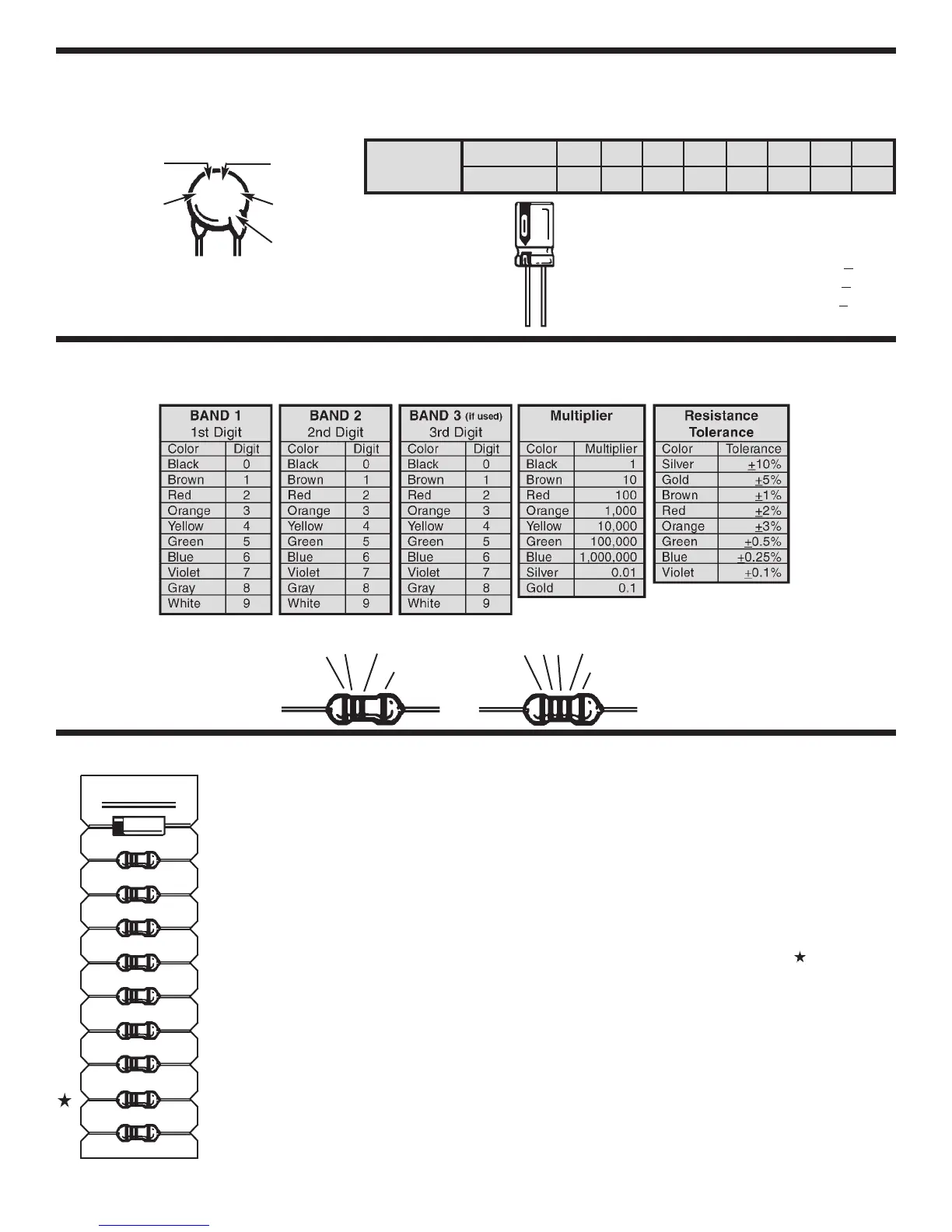
IDENTIFYING RESISTOR VALUES
Use the following information as a guide in properly identifying the value of resistors.
SECTION A
5 Bands
1 2
Multiplier
Tolerance
3
4 Bands
1
2
Multiplier
Tolerance
-8-
EXAMPLE
IDENTIFYING CAPACITOR VALUES
Capacitors will be identified by their capacitance value in pF (picofarads), nF (nanofarads), or mF (microfarads). Most
capacitors will have their actual value printed on them. Some capacitors may have their value printed in the following
manner. The maximum operating voltage may also be printed on the capacitor.
Second Digit
First Digit
Multiplier
Tolerance*
For the No.01234589
Multiply By 1 10 100 1k 10k 100k .01 0.1
Multiplier
Note: The letter “R” may be used at times to
signify a decimal point; as in 3R3 = 3.3
10mF 16V
103K
100V
The letter M indicates a tolerance of +20%
The letter K indicates a tolerance of +
10%
The letter J indicates a tolerance of +5%
Maximum Working Voltage
The value is 10 x 1,000 =
10,000pF or .01mF 100V
*
 Loading...