III
CONTENTS
1. INTRODUCTION ...................................................................................................... 5
2. WARNINGS ............................................................................................................ 6
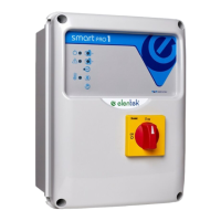
3. OVERVIEW ............................................................................................................. 7
4. INSTALLATION ........................................................................................................ 9
5. LIGHT INDICATORS AND COMMANDS .................................................................. 10
6. MAIN BOARD INPUTS AND OUTPUTS................................................................... 11
7. EXPANSION INPUTS ............................................................................................. 13
7.1 RS485 expansion ............................................................................................................ 13
7.2 Voltage-free contact output expansion ......................................................................... 13
7.3 Probe input expansion for motor start .......................................................................... 13
7.4 Probe input expansion for water seepage into oil chamber .......................................... 13
7.5 Buffer battery device expansion .................................................................................... 13
7.6 Bluetooth-WIFI expansion ............................................................................................. 14
8. MOTHERBOARD DIP-SWITCH SETTINGS ............................................................... 15
8.1 DIP-SWITCH 1 - level alarm signalling from probe input ............................................... 15
8.2 DIP-SWITCH 2 - Ammeter trip delay............................................................................... 15
8.3 DIP-SWITCH 3 - Klixon input deactivation ...................................................................... 16
8.4 DIP-SWITCH 4 - Alarm reset enable from motor Klixon ................................................. 16
8.5 DIP-SWITCH 5 - Filling/Emptying mode probe input ...................................................... 16
8.6 DIP-SWITCH 6 - Self-holding enable (start/stop floats) .................................................. 17
8.7 DIP-SWITCH 7 - Delayed board activation enable on mains power return .................... 17
8.8 DIP-SWITCH 8 - Motor switching module enable ........................................................... 18
9. DIP-SWITCH SETTINGS DISPLAY............................................................................ 19
9.1 DIP-SWITCH 1 - NO/NC (G/P1 - G/P2 - G.A.) Input reversal ........................................... 19
9.2 DIP-SWITCH 2 - Phase sequence control exclusion ........................................................ 19
9.3 DIP-SWITCH 3 - Self-test enable ..................................................................................... 19
9.4 DIP-SWITCH 4 - Manual push or impulse key ................................................................. 20
10. TRIMMER SETTINGS ......................................................................................... 21
10.1 TRIMMER SENS. PROBE - Probe sensitivity .................................................................... 21