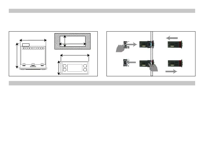
MECHANICAL ASSEMBLY
The instrument is designed for panel mounting. Make a hole of 29x71 mm, insert the instrument and fix it using the
brackets provided. Do not mount the instrument in humid and/or dirty places; it is suitable for use in ordinary polluted
places. Ventilate the place in proximity to the instrument colling slits.
ELECTRICAL WIRING
Attention! Never work on electrical connections when the machine is switched on.
The instrument is equipped with screw terminal boards for connection of electrical cables with a diameter of 2.5 mm
2
(one
conductor only per terminal for power connections). For the capacity of the terminals, see the label on the instrument. In the
model ID 974 with Switching power supply only one voltage free relay output is present, on all other models on the contrary all
relay outputs are voltage free. Do not exceed the maximum current allowed; in case of higher loads, use an appropriate contactor.
Make sure the power supply voltage complies with the one required by the instrument. In 12V versions the power supply must
be provided by a security transformer with the protection of a delayed 250 mA fuse. Probes have no connection polarity and can
be extended using a regular bipolar cable (note that the extension of the probes affects the EMC electromagnetic compatibility
of the instrument: pay extreme attention to wiring). Probe cables, power supply cables and the TTL serial cables should be distant
from power cables.
12