905U Wireless I/O Module User Manual
105S Serial I/O Module
Page 14 © January 2011
The Yagi gain also acts on the receiver, so adding Yagi antennas at both ends of a link provides a
double improvement.
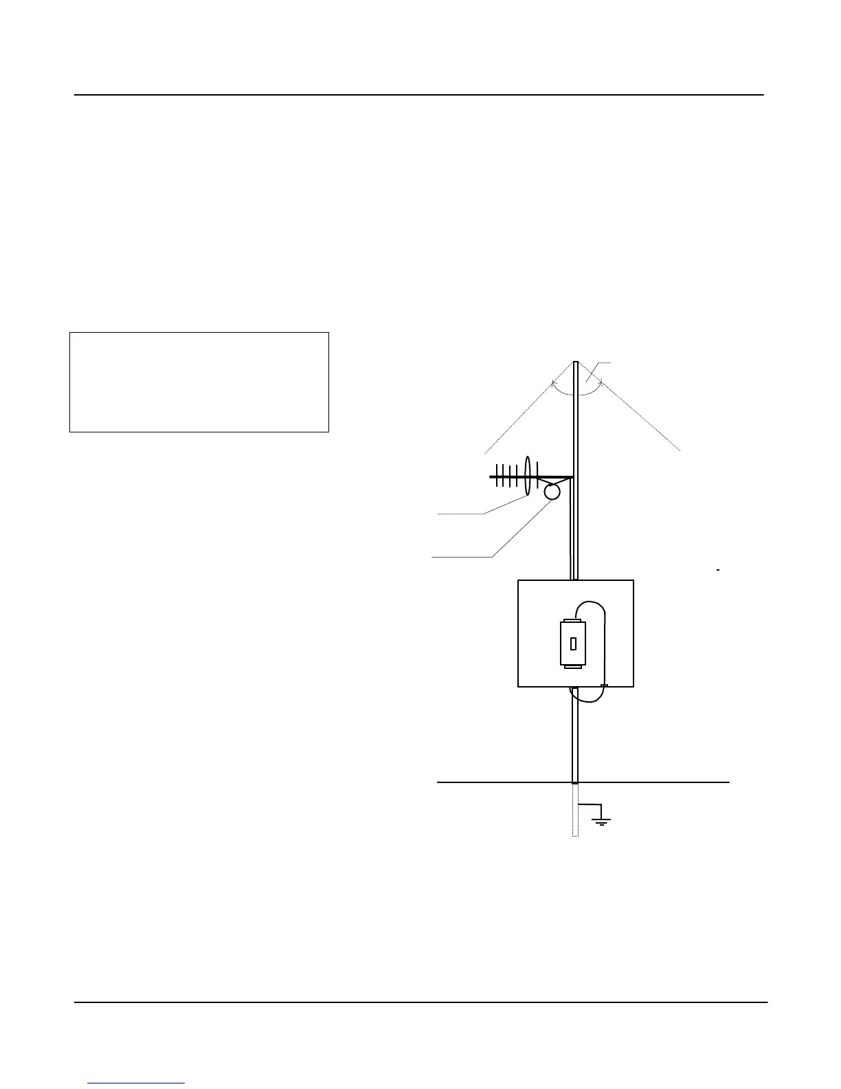
Yagi antennas are directional. That is, they have positive gain to the front of the antenna, but negative
gain in other directions. Hence Yagi antennas should be installed with the central beam horizontal and
must be pointed exactly in the direction of transmission to benefit from the gain of the antenna. The
Yagi antennas may be installed with the elements in a vertical plane (vertically polarised) or in a
horizontal plane (horizontally polarised). For a two station installation, with both modules using Yagi
antennas, horizontal polarisation is recommended. If there are more than two stations transmitting to a
common station, then the Yagi antennas should have vertical polarisation, and the common (or
“central” station should have a collinear (non-directional) antenna.
Note that Yagi antennas normally
have a drain hole on the folded
element - the drain hole should be
located on the bottom of the
installed antenna.