905U Wireless I/O Module User Manual
105S Serial I/O Module
Page 16 © January 2011
negatively grounded.
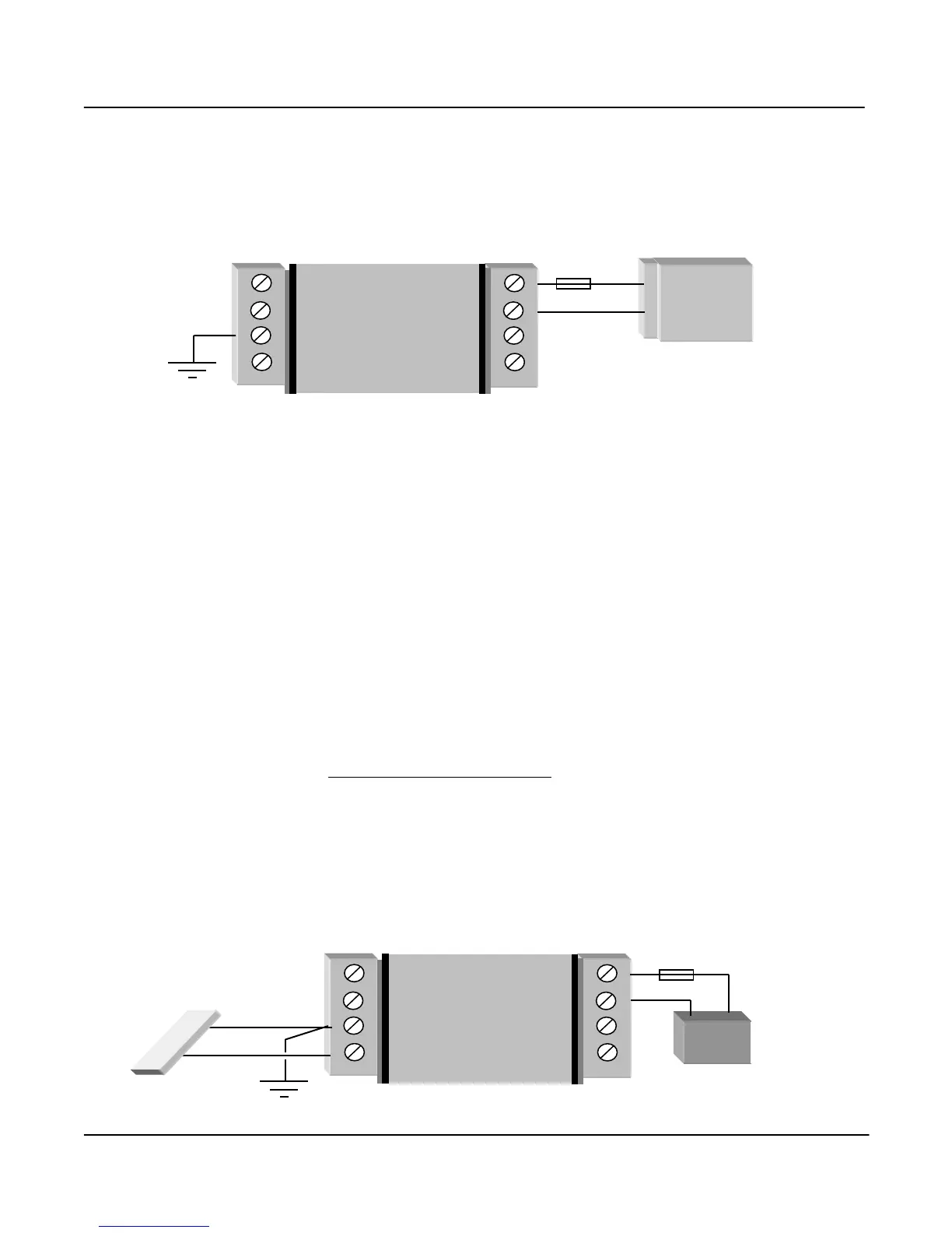
The module may also be powered from an external 11.5 - 15 VDC battery supply without the need for a
"normal" supply connected to "SUP1". This external battery supply is connected to "BAT+" and
"GND" terminals. The positive lead of the external supply should be protected by a 2A fuse.
Upon failure of the normal supply, the module may continue to operate for several hours from a backup
battery. The module includes battery charging circuits for charging up to a 12 AHr sealed lead acid
battery. The battery is connected to the "BAT+" (positive) and "GND" (negative) terminals. The
positive lead from the battery should be protected with a 2A fuse, installed as near to the battery
terminal as possible. On return of main supply, the unit will switch back to mains operation, and
recharge the battery. To provide adequate current to recharge the backup battery, an AC supply of 15V
minimum or a DC supply of 17V minimum must be used. Typically, a 6 AHr battery will supply the
905U for 1 - 3 days, depending on I/O loads.
2.3.3 Solar Supply
The power supply also includes a 12 V solar regulator for connecting 12V solar panels of up to 30W,
and solar batteries of up to 100AHr. The unit must not be powered from a solar panel without a
battery. A 20W solar panel is sufficient for most solar applications. The size of the solar battery
required depends on the I/O used. Batteries are sized for a number of sunless days with 50% battery
capacity remaining as follows:
No. of sunless days = Battery capacity (AHr) x 0.5
Module load (A) x 1.2 x 24
The Module load depends on the I/O connected and can be calculated as follows:
Module Load(mA) = (85 for 105U/905U or 45 for 105S) + (10 x No. of active DI’s) +
(25 x No. of active DO’s) + (2 x Analog loop load).
The analog loop load is the total signal current for the AI’s and AO’s which are powered from the
internal 24V supply. Externally powered loops are not included in this.