Chapter Three Operation
man_905-105_2.16 Page 27
Chapter Three OPERATION
3.1 Power-up and Normal Operation
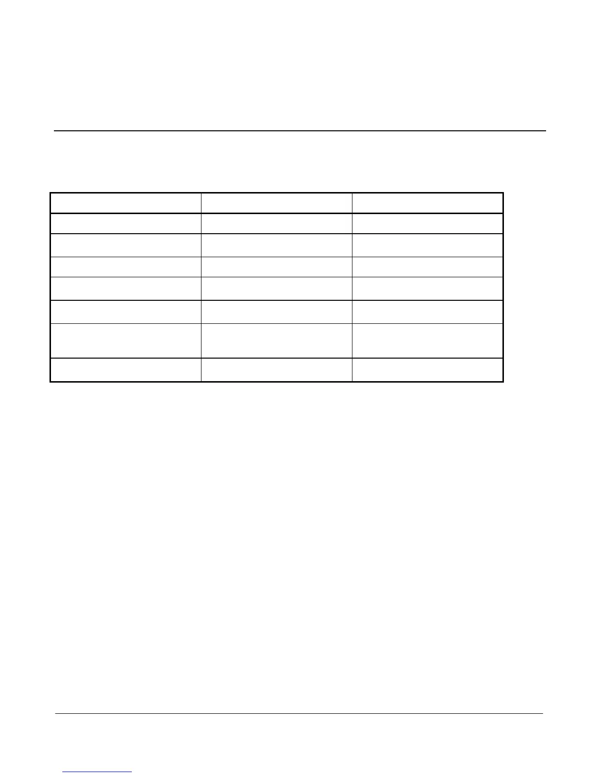
When power is initially connected to the module, the module will perform internal diagnostics to check
its functions. The following table details the status of the indicating LED’s on the front panel under
normal operating conditions.
Additional LED’s provide indication of the status of digital inputs and outputs. LED’s display the status of
each digital input (lit for active), and LED’s display the status of each digital output (lit for active). Other
conditions indicating a fault are described in Chapter Six Troubleshooting.
The module monitors the power supply and provides status of supply failure and battery low voltage
for "mapping" to one of the module's own outputs or transmitting to a remote output. When the
module is powered from a normal supply (i.e. via either of the “SUP” terminals), the PWR LED
indicator is lit. When the modules is powered from a solar panel and battery, the PWR LED indicator
is lit only when the charge current is available (i.e. when the solar panel is receiving light).
If a backup battery is connected, the module will generate a low battery voltage status when the
voltage has dropped to 11.3V for approx 45 seconds. This status may be transmitted to another
module. In the event of excessively low battery voltage (10.8V), the OK LED will go off, the unit will
automatically set all outputs off, and disable the +24V analog loop supply. the OK LED will turn on
again after the battery voltage exceeds 11.8V. This enables installations to be configured so that the
battery current drain is minimised in the event of extended mains failure, reducing the possibility of
deep discharge of batteries.
3.1.1 Communications
Before each transmission, the 905U radio will “listen-before-transmit” to make sure that another
module is not already transmitting - if there is another transmission, the 905U will wait until the