Chapter Two Installation
man_905-105_2.16 Page 25
2.4.10 RS232 Serial Port
The serial port is a 9 pin DB9 female and provides for connection to a terminal or to a PC for
configuration, field testing and for factory testing. This port is internally shared with the RS485 -
ensure that the RS485 is disconnected before attempting to use the RS232 port. Communication is via
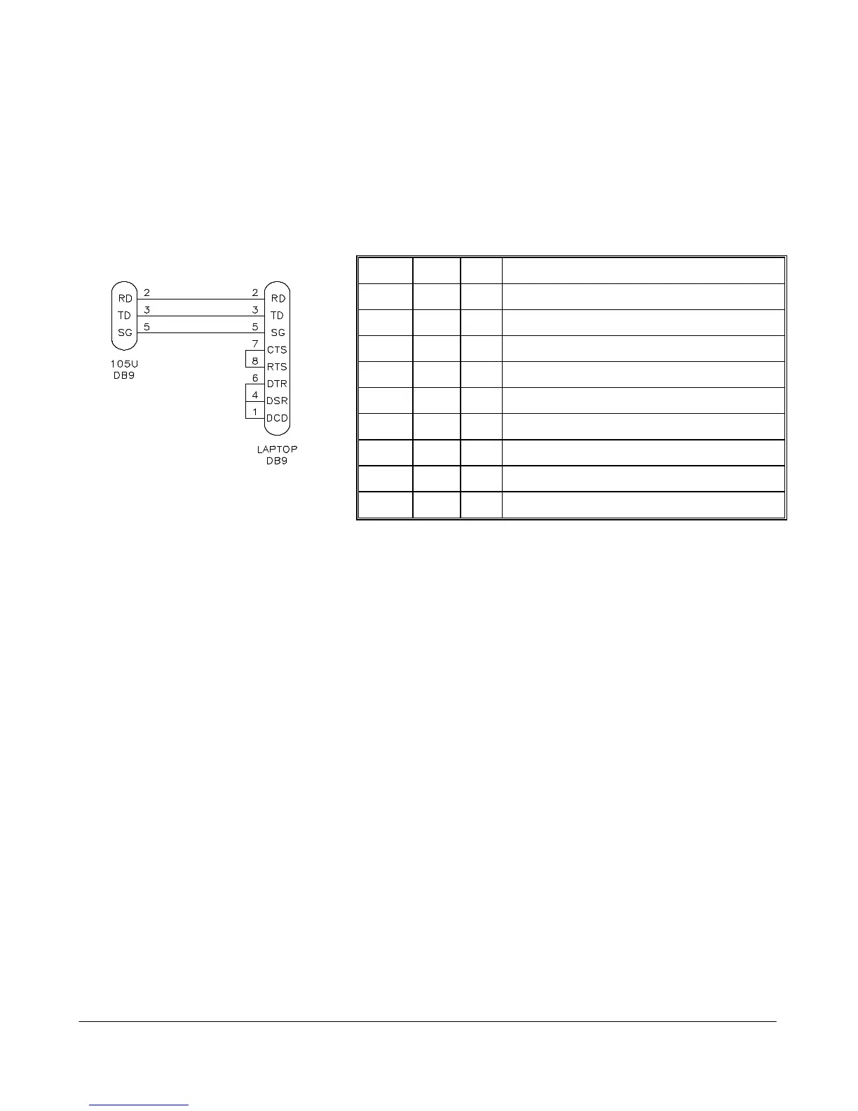
standard RS-232 signals. The 905U/105S is configured as DCE equipment with the pin-out detailed
below. The serial port communicates at a baud rate of 9600 baud, 8 bits, no parity, one stop bit. An
example cable drawing for connection to a laptop is detailed below:
Pin Name Dirn Function
1 DCD Out Data carrier detect - not used
2 RD Out Transmit Data - Serial Data Input (High = 0, Low = 1)
3 TD In Receive Data - Serial Data Output (High = 0, Low = 1)
4 DTR In Data Terminal Ready - not used
5 SG - Signal Ground
6 DSR Out Data Set Ready - not used
7 RTS In Request to Send - not used
8 CTS Out Clear to send - not used
9 RI - Ring indicator - not used.
2.4.11 RS485 Serial Port
The RS485 port provides for communication between multiple units using a multi-drop cable. Up to 32
units may be connected in each multi-drop network. Each multi-drop network may have one unit
providing radio communications with other units in the system. The RS485 feature allows local hubs of
control to operate without occupying radio bandwidth required for communication between remotely
sited units.
The RS485 Communications format is 9600 baud, 8 data bits, one stop bit, no parity. Note that the
RS485 port is shared internally with the RS232 port - disconnect the RS232 cable after configuration is
complete.
RS485 is a balanced, differential standard but it is recommended that shielded, twisted pair cable be
used to interconnect modules to reduce potential Radio Frequency Interference (RFI). An RS485
network should be wired as indicated in the diagram below and terminated at each end of the network
with a 120 ohm resistor.