Chapter Two Installation
man_905-105_2.16 Page 21
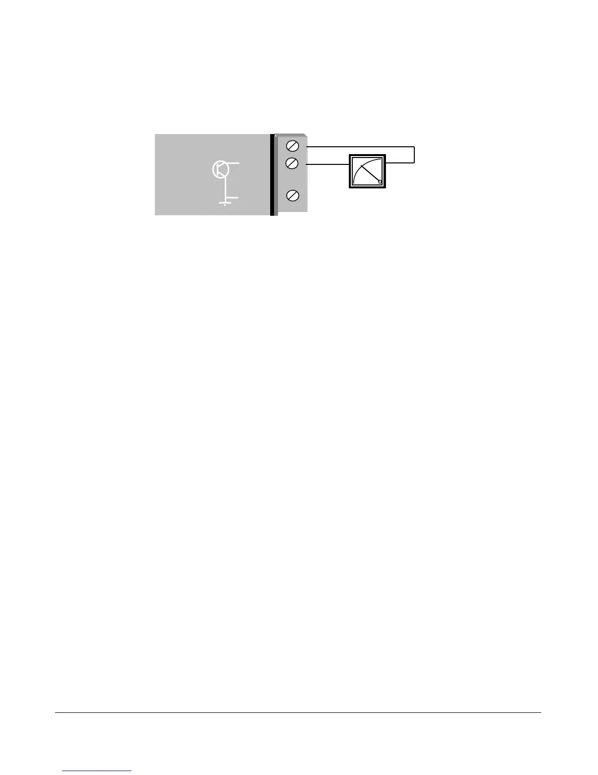
2.4.5 Analog Outputs (905-1 and 905-3)
The ”-1” module provides two 4 - 20 mA DC analog outputs for connecting to instrument indicators for
the display of remote analog measurements. The ”-3” module provides eight 0 - 20 mA DC analog
outputs. Each analog output is a "sink" to common.
A 24VDC supply is available on the module for powering the analog output loop (max external loop
resistance 1000 ohms). In this case, the analog loop is connected between a "+24V" terminal and "AO
1" ( for the first analog output) or "AO 2" (for the second analog output), and so on for the other
output signals.
If connecting to an external device such as an electronic indicator, recorder or PLC / DCS input, the
loop can be powered be either the 905U or the device. Externally powered loops to 27 VDC may be
connected by connecting the output between the "AO” terminal (positive) and the "COM" terminal
(negative). Zener protection of analog outputs provides protection against short periods of over-voltage
but longer periods may result in module damage.
Note that the common is connected internally to ground and no other point in the analog loop should
be grounded. If the external device has single-ended grounded inputs, then a signal isolator must be
used.
Analog outputs may also be configured to individually turn off (0 mA) if no command message is
received to that output for a certain period. . See Chapter 4 Configuration for further details.