905U Wireless I/O Module User Manual
105S Serial I/O Module
Page 20 © January 2011
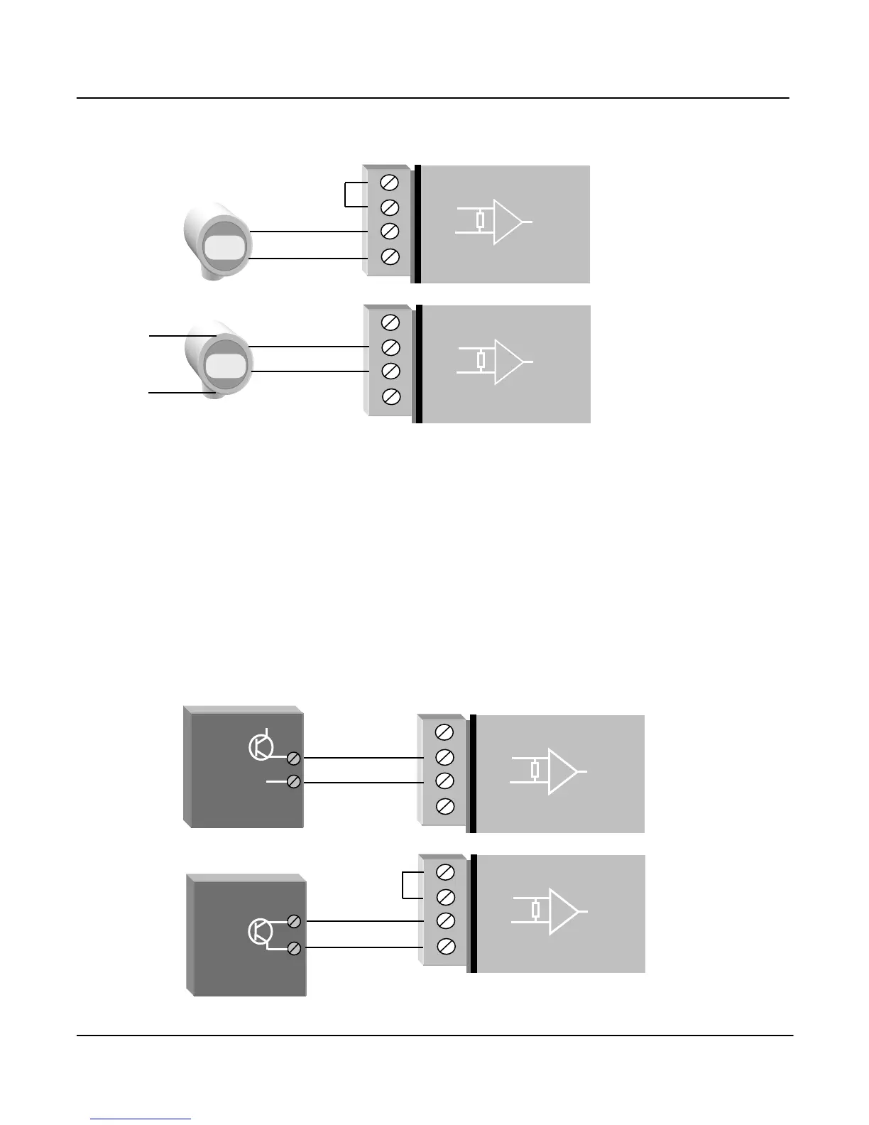
The positive terminal ("AI 1+" or "AI 2+", etc) should be connected to "+24V".
Externally powered loops may be connected by connecting the input between "AI 1+" and “AI 1-” for
analog input 1 or "AI 2+" and “AI 2-” for analog input 2, and so on for other inputs. Common mode
voltage may be -0.5V to 27V.
Shielded cable is recommended for analog I/O loops to minimise induced noise and Radio Frequency
Interference (RFI). The shield of the cable should be connected to earth at one of the cable only. The
use of shielded wiring inside an enclosure containing a module is also recommended.
To connect an AI on the 905U to an analog signal from a PLC or DCS output, check the internal
circuit of the output carefully as different devices use different ways to create an analog signal. The
following diagram shows two ways of connecting.