Chapter Two Installation
man_905-105_2.16 Page 17
The solar panel is connected to the "SOL" (positive) and "GND" (negative) terminals and the battery
connected to the "BAT+" (positive) and "GND" (negative) terminals. Solar panels must be installed
and connected as per the panel manufacturer's instructions. The positive lead of the battery should be
protected by a 2A fuse installed as near as possible to the battery terminal.
Where a panel larger than 30W is required, an external solar regulator should be used.
For maintenance, disconnect the solar panel first before disconnecting the battery.
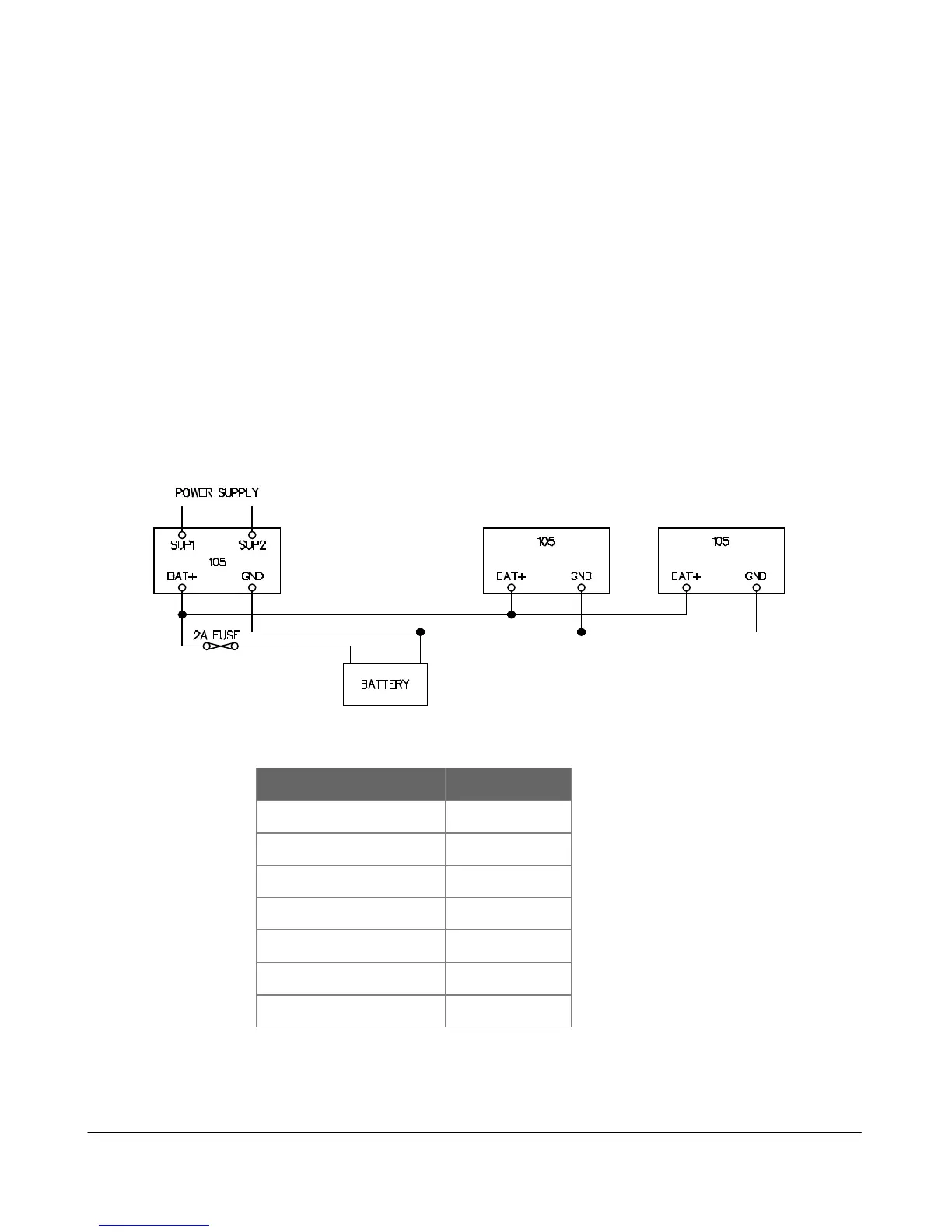
2.3.4 Multiple Modules
Where more than one module is installed at the one location, a shared power supply and battery may
be used, provided the total load does not exceed the power supply.
The internal power supply of the module can supply a maximum 12V load of 700mA. In order to
achieve this, the input power supply must be above 15VAC or 17VDC. Using these figures, it can be
determined whether there is enough supply for more than one module - allow 100mA for
recharging a battery.
For example, assume there is a 905U-1 module and a 105S-1 module at the same location. The total
I/O at the location is 3 analog inputs, 6 digital inputs and 4 digital outputs. The total load will be :-
TYPE OF LOAD LOAD mA
905U-01 quiescent 85
105S-01 quiescent 45
6 DI @ 10 mA 60
3 AI @ 20mA x 2 120
4 DO @ 25mA 100
Battery charging 100
TOTAL 510
So both modules could be powered from one power supply and one battery, provided the external
supply voltage is more than 15VAC or 17VDC.