13
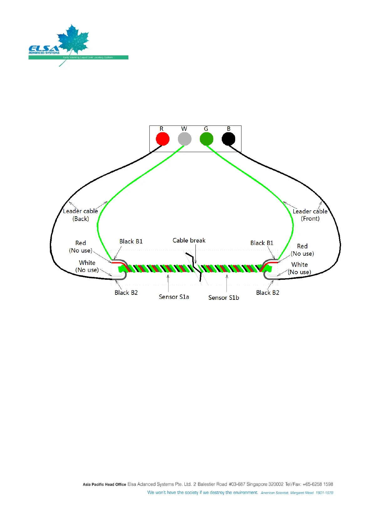
There shall be two wires (green & black) from the Leader cable (Back), connect the black wire to ‘R’
terminal and connect the green wire to ‘W’ terminal.
There shall be two wires (green & black) from the Leader cable (Front), connect the green wire to
‘G’ terminal and connect the black wire to ‘B’ terminal.
Connect wire coloring code as per above figure when fail-safe loop back connection method is
selected instead of normal end-termination method.
When the black wire (B2 as per above diagram) on the white-black pair of the sensing cable is
broken and the black wire (B1 as per above diagram) on red-black pair remain connected, the
system is still able to detect and locate the leak.
When both wires are broken at any one point of the cable, either side (S1a or S1b as per above
diagram) of the cable is still able to detect leak but it shall not provide the leak location.
Figure 8: Fail-safe cable connection details