6
Point - Representing Alarm “Sound OFF” action or as digit # “5”.
Point C - - Representing “System LCD display, displays the operation process of 3L-SP/AP panel.
Point B - - Representing “Power LED”.
Point D - - Representing “Leak LED”.
Point C - - Representing “Trouble LED”.
Point B - - Representing DIP switch. Always default number #1.
Point D - - Representing sensitivity adjustment.
Point C - - Representing sensing cable total length adjustment.
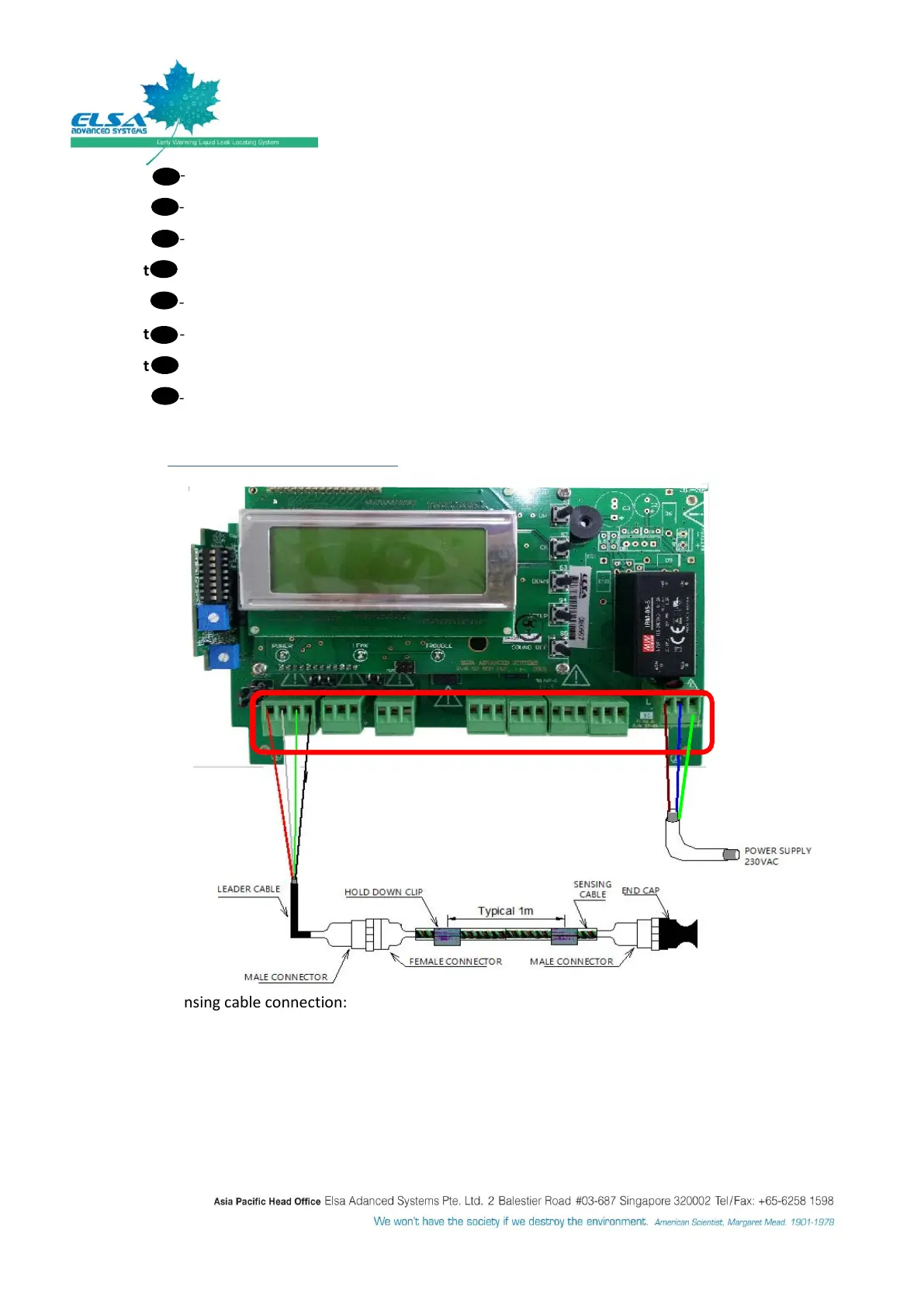
1.2.2 CABLE CONNECTION DETAILS
Sensing cable connection:
Follow the color code such as R-Red, W-White, G-Green & B-Black by using leader cable.
Output (To Panels):
N.A
MODBUS (To 3L/SP,3L-SP/DP,BMS OR EMS):
Connect RS485 communication cable to Building Management System (BMS) or
Environment Management System (EMS).
Figure 2: Schematic diagram for 3L-SP/AP with one zone