5
Trouble Relay – NO
(Normally Open)
Trouble Relay – NC
(Normally Close)
Leak Relay – NO
(Normally Open)
Leak Relay – NC
(Normally Close)
Leak Relay – NO
(Normally Open)
Leak Relay – NC
(Normally Close)
AC Supply 100-240V - LIVE
Trouble Relay – NO
(Normally Open)
AC Supply 100-240V - NEUTRAL
AC Supply 100-240V - EARTH
Trouble Relay – NC
(Normally Close)
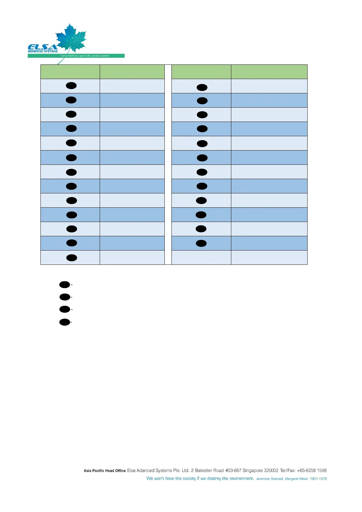
Point A - - Representing move “UP” action or as digit # “1”.
Point B - - Representing “OK” action or as digit # “2”.
Point D - - Representing move “Down” action or as digit # “3”.
Point C - - Representing System Menu for “Setup” action or as digit # “4”.
When pressing “Setup” button, the LCD display will show a list of System Menu to select.
Sensor Lengths: It shall show the length of sensing cable of each monitoring zone
System Parameters:
Sound ON/OFF Setup (Password protected: Default password is “12341234”)
- To permanently turn ON or OFF the Alarm/Buzzer.
System Setup (Password protected: Default password is “12341234”)
- Modbus Interface
o For interfacing with high level Building Management System (BMS) or SP
panel. Can assign from 1 to 100 numbers of code.
- Time/Date Setup
o To set or adjust Time and Date.