8
Cable Break Test:
Disconnect the end termination point (Remove end cap)
Check red “Trouble” LED turns ON.
Check display “CABLE BREAK”.
Check Buzzer intermittent sound.
Trouble Relay/Dry Contact will be activated.
Reconnect end termination point.
Check 3L-SP/AP, it will clear the fault automatically and the “Trouble” LED turns OFF, Buzzer
stops sounding and display “CABLE BREAK CLEARED” then comes back to normal.
LCD display will show “Date, Time and SUPERVISION (ON)”
Note: During Cable Break, 3L-SP/AP still able to detect all preceding cables for leakage alarm.
1.4 FALSE ALARM TROUBLESHOOTING
Cable break alarm
Check the entire cable length for a cut or shearing which cause cable break.
Check all 4 wires (R, W, G, B) connections on sensing cable for continuity by a multi-meter.
o By using the multi-meter measure the cable resistance (Red &black, white & greed).
The resistance for sensing cable is 25 Ohm/meter.
Leakage alarm
Check the sensing cable for proper installation and avoid contact with metals (or other
conductive elements) which cause leak.
Check sensing cable to identify any badly contaminated by some chemical for unknown
reason.
If the false alarm still not clear Refer CHAPTER 6troubleshooting guide.
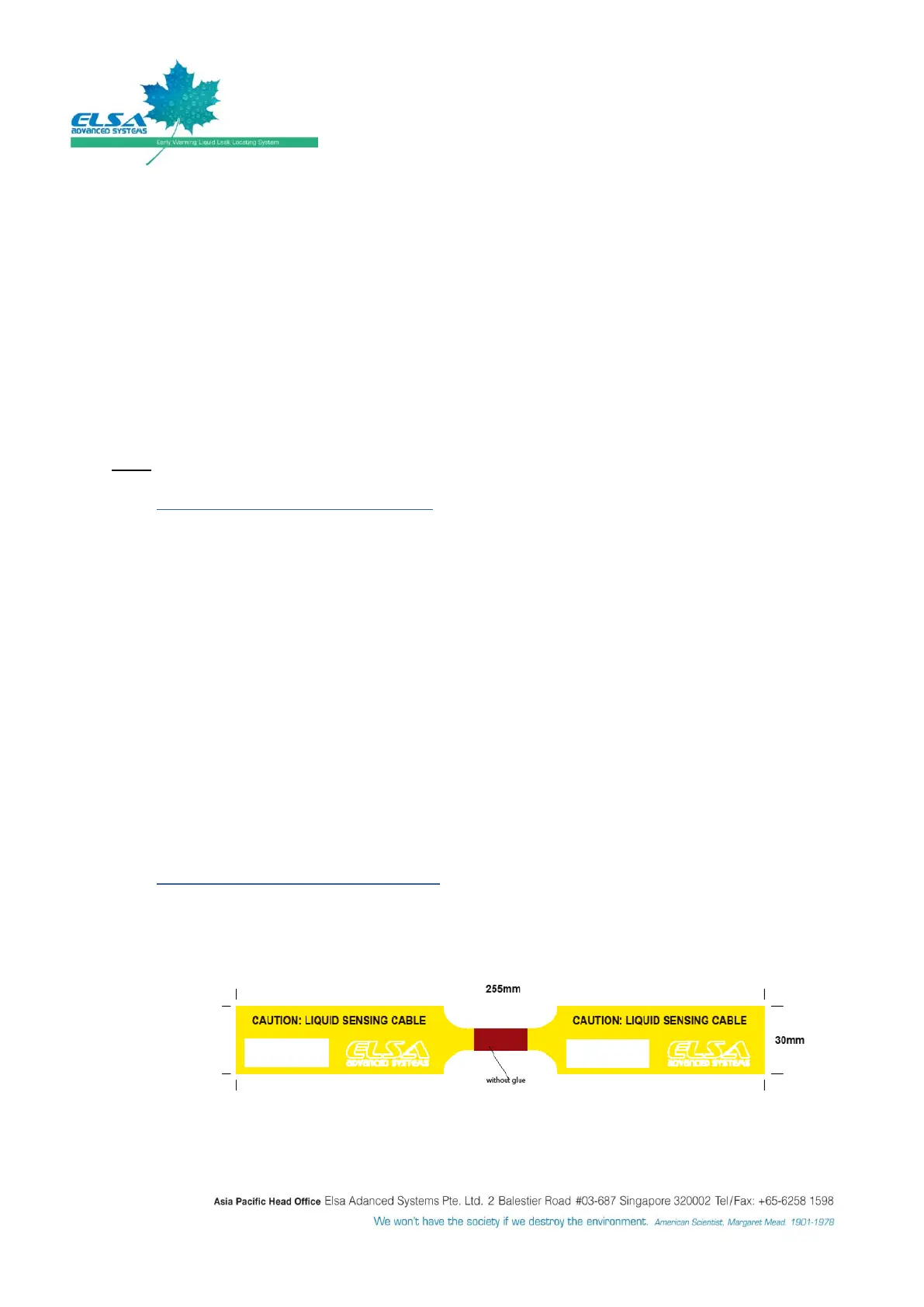
1.5 TAG OR LABEL FOR SENSING CABLE
It is recommended to place 3m to 5m per tag or label.
To determine the tag or label location exactly, simulate a leak at that point and get the leak
location from 3L-SP/AP panel. Write the distance on the tag or label.
Figure 3: 3L-Tag for sensing cable