06/2022
| 30 |
924EHUCE4.00 - Mistral Humidier
6.2.2 Wiring guidelines
Whenwiringthecontrollers,observethefollowingstandards:
• TheI/Oandcommunicationwiringmustbekeptseparatefromthepowersupplywiring.Thesetwotypesofwiringmust
be routed in separate ducts.
• Makesuretheoperatingenvironmentandconditionsfallwithinthespeciedvalues.
• Usewireswiththecorrectdiameter,suitedtothevoltageandcurrentrequirements.
• Use copper conductors (compulsory).
• Use shielded twisted pair cables for analogue/digital I/O connections.
Use correctly earthed shielded cables for all analogue inputs and for communication connections. If shielded cables are not
usedfortheseconnections,electromagneticinterferencemaycausesignaldegradation.
Degraded signals can result in unpredictable operation of the controller or the modules and connected equipment.
WARNING
MALFUNCTIONING OF THE EQUIPMENT
• Perform the wiring carefully and in compliance with electromagnetic compatibility and safety requirements.
• Makesurethewiringiscorrectfortheendapplication.
• Minimisethelengthoftheconnectionsasmuchaspossible,toavoidwindingthecablesaroundelectricallyconnectedparts.
• Beforeapplyingthepowersupply,checkallthewiringconnections.
• Donotconnectcablestounusedterminalsand/orterminalsmarkedwiththetext“Noconnection”(N.C.).
6.2.3 Guidelines for screw terminal blocks
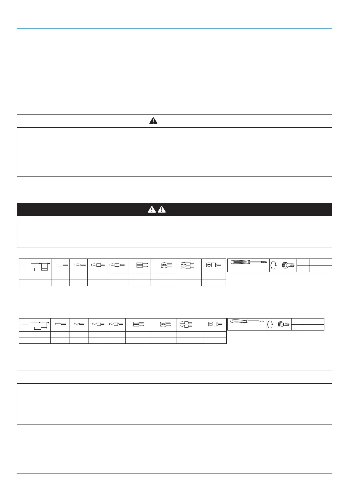
Suitable wiring for the power supply
DANGER
RISK OF ELECTRIC SHOCK
• Cutoffthepowersupplytoallequipment,includinganyconnecteddevices,beforeremovinganycoversorhatches,or
beforeinstalling/uninstallingaccessories,hardware,fuses,cablesorwires.
• AlwaysuseaproperlycalibratedVoltmetertomakesurethesystemispoweredoff.
Ø 3.5 mm (0.14 in.)
mm
2
0.2…2.5
24…14
0.2…2.5
24…14
0.25…2.5
22...14
2 x 0.25…1
2 x 22…18
2 x 0.2…1.5
2 x 24…16
2 x 0.2…1
2 x 24…18
2 x 0.5...1.5
2 x 20...16
mm
in.
7
0.28
C
0.5...0.6
4.42...5.31
N•m
lb-in
0.25…2.5
22...14
Fig. 16. Suitable wiring for the power supply
Suitable wiring for I/O SELV
Ø 3.5 mm (0.14 in.)
mm
2
0.14…1.5
25…15
0.14…1.5
25…15
0.25…1.5
22...15
2 x 0.25…0.34
2 x 23…21
2 x 0.08…0.5
2 x 28…20
2 x 0.08…0.5
2 x 28…20
2 x 0.5...0.5
2 x 20...20
mm
in.
7
0.28
C
0.5...0.6
4.42...5.31
N•m
lb-in
0.25…0.5
22...20
Fig. 17. Suitable wiring for I/O SELV
6.2.4 Permitted cable lengths
NOTICE
MALFUNCTIONING OF THE EQUIPMENT
• Whenconnectingthepowersupply,usecablesthatarenolongerthan10m(32.80ft.).
• Whenconnectingthesensors,digitalinputsandanalogueinputs,usecablesthatarenolongerthan10m(32.80ft.).
• WhenconnectingtheRS-485serialline,usecablesthatarenolongerthan1000m(3280ft).
• Whenconnectingthedigitaloutputs,usecablesthatarenolongerthan10m(32.80ft).


 To Next Page