Primary Switch Mode Rectifier
PSS30
User manual
Page 11 (28)
Eltek Valere Industrial ©2008 UM_PSS30_E_R00
5.2.4 Dynamic regulation of the output voltage
At load jumps between 10 % and 90 % I
nom
/ 90 % and 10 % I
nom
the dynamic voltage difference is max.
± 3 % and is corrected in max. 1,5 ms to static levels.
5.2.5 RFI suppression
Modules of type PSS meet the standard VDE 0878 T1 and EN 55011/55022 class ‘B’. The output ripple
is (psophometrically measured according to CCITT) < 1mV (24V), < 1,8mV (48V) and <2mV (60V).
5.2.6 CAN-Bus interface
The rectifier PSS is equipped with a serial CAN-Bus interface. Two CAN connectors (RJ11, 6-pole) are
fitted at the front side of the 24V - 110V version. For the 220V version the CAN-Bus connection is inte-
grated in the front side connector X4.
Several modules in a system or parallel connection can be controlled and monitored through the CAN-
Bus by a central DC controller unit MU1000C.
The following parameters of a specific rectifier unit can be controlled or monitored:
• Output voltage
• Output current
• Module status
Furthermore, the rectifier unit receives all threshold values through the CAN-Bus from the
DC controller unit.
REMARK: If several paralleled rectifiers are controlled by a central DC controller unit, it is important to
assign an explicit CAN-Bus address to each individual rectifier (see section 5.4).
5.3 Monitoring
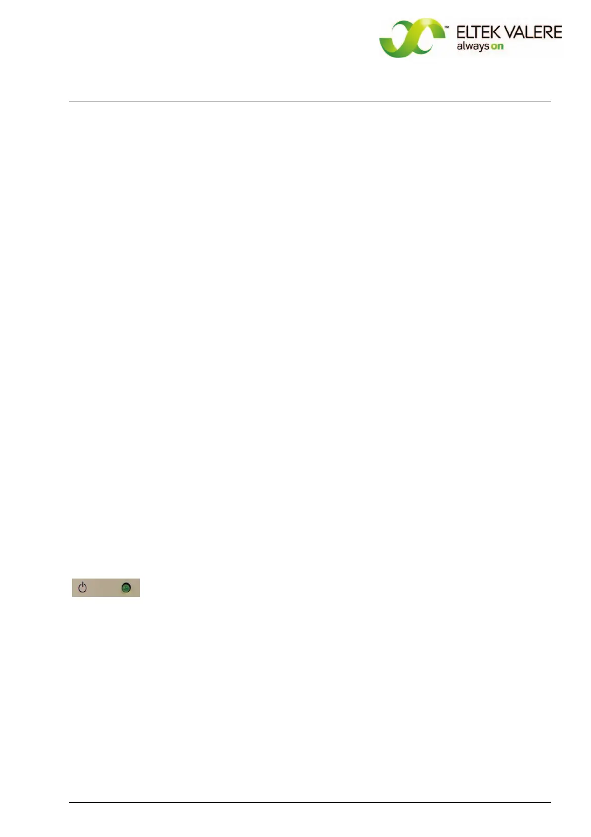
5.3.1 Mains voltage monitoring
Mains voltage monitoring; signalling with LED "Switch symbol", criterion: output voltage of step-up-
converter ≥ 370 V, at the same time operation monitoring of step-up-converter (equivalent to main
voltage of approx. ≥ 195 VAC; depends on the load).
The LED is dark if the mains voltage is low or the step-up-converter is out of order.
This signal is included in the collective failure signal of the rectifier. Additional there is an optocoupler
signal (mains O.K.).
For high input voltages (approx. >270V
AC) there is implied an automatic switch off function.
 Loading...